3D printing system applicable to high-viscosity liquid chemical mixing formation

A hybrid molding and 3D printing technology, applied in the field of 3D printing, can solve the problems of expensive 3D printers, low heat dissipation efficiency, and inability to dissipate heat, so as to improve the appearance quality and internal structure quality, improve mixing efficiency and mixing uniformity, The effect of improving heat dissipation efficiency and heat dissipation uniformity

Inactive Publication Date: 2018-05-04
北京中科三维科技有限公司
View PDF4 Cites 2 Cited by
  • Summary
  • Abstract
  • Description
  • Claims
  • Application Information

AI Technical Summary

Problems solved by technology

[0007] In order to further expand its industrial application space, 3D printing technology still faces many bottlenecks and challenges: First, in terms of cost, the cost of existing 3D printers is generally relatively expensive, which brings difficulties to its further popularization and application
Second, in terms of printing materials, most of the molding materials for 3D printing currently use chemical polymers, the selection is limited, the physical properties of the molded products are poor, and there are certain hidden dangers in terms of safety.
The third is precision, speed and efficiency. At present, the precision of 3D printed products is not satisfactory, and the printing efficiency is far from meeting the needs of mass production. Moreover, due to the limitation of the working principle of the printer, there is a serious conflict between printing precision and speed.
Fourth, in terms of industrial environment, the popularization of 3D printing technology will make it easier for products to be copied and spread. The risk of piracy in the manufacturing industry will increase greatly. The existing intellectual property protection mechanism will not be able to meet the needs of the future development of the industry.
[0008] At present, the existing 3D printing system for high-viscosity liquid chemical hybrid molding mainly has the following disadvantages: In terms of defoaming and exhausting treatment of high-viscosity liquid materials, the existing exhaust method applied to 3D printing of high-viscosity liquid materials , the main method is to add a defoamer to the high-viscosity liquid to achieve the purpose of defoaming and exhausting. This chemical defoaming and exhausting method cannot completely and effectively eliminate the bubbles in the liquid.
The heat dissipation efficiency of this method is not high, because it is powered by the motor, which has a certain amount of noise. The longer the fan runs, the louder the noise
Due to the mechanical structure, it takes up a lot of space, and it is inconvenient to install near the 3D printing head, which seems to have a small space.
Once the blade fan is installed, the blowing direction is fixed, it can only dissipate heat in a single direction, and cannot dissipate heat in a 360-degree direction around the print head
There is a problem of uneven heat dissipation
Furthermore, the blade-type mechanical fan only has the single function of heat dissipation, and cannot perform dust removal and purification on the air inside the 3D printer, nor does it have the function of eliminating static electricity in the internal space.

Method used


Image

  • 3D printing system applicable to high-viscosity liquid chemical mixing formation
  • 3D printing system applicable to high-viscosity liquid chemical mixing formation

Examples


Embodiment Construction

[0029] In order to make the implementation technical means, creative features, objectives and effects of the present invention easy to understand, the present invention will be further elaborated below in conjunction with specific illustrations.

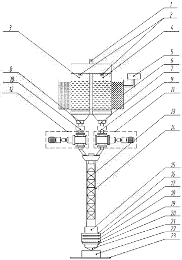
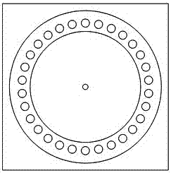
[0030] Such as figure 1 , figure 2 As shown, a 3D printing system suitable for high-viscosity liquid chemical hybrid molding, including: storage tank I3, storage tank II4, the upper side of the storage tank I3, storage tank II4 is equipped with an ultrasonic generating device 2 The upper ends of the storage tank I3 and II4 are provided with an exhaust port 1, the lower side of the storage tank I3 is provided with a high-viscosity liquid feed pump I12, and the lower side of the storage tank II4 is provided with a high-viscosity liquid supply pump. Material pump II11, the high-viscosity liquid feed pump I12, and the lower end of the high-viscosity liquid feed pump II11 are connected to the mixing barrel 14 through a three-way pipe. T...


PUM


Abstract

The invention provides a 3D printing system applicable to high-viscosity liquid chemical mixing formation. The 3D printing system applicable to high-viscosity liquid chemical mixing formation comprises a first storage tank and a second storage tank. Ultrasonic wave generating devices are arranged on the upper side of the first storage tank and the upper side of the second storage tank. An exhaustoutlet is formed in the upper ends of the first storage tank and the second storage tank. The lower side of the first storage tank is provided with a first high-viscosity liquid supply pump, the lowerside of the second storage tank is provided with a second high-viscosity liquid supply pump, and the lower ends of the first high-viscosity liquid supply pump and the second high-viscosity liquid supply pump are connected to a mixing barrel through a tee pipe. A static mixer is arranged in the mixing barrel. The lower end of the mixing barrel is provided with a printing head, and a circular air outlet is formed in the printing head. A circular air inlet is formed in the position, on the upper side of the circular air outlet, of the printing head. The lower side of the printing head is provided with a printing platform, and a printed piece is disposed on the printing platform. By means of the 3D printing system applicable to high-viscosity liquid chemical mixing formation, chemical reaction is accelerated, the appearance quality and interior structure quality of the printed piece are finally improved, at the same time, supply is more stable, vibration is small, and noise is low.

Description

technical field [0001] The invention relates to the technical field of 3D printing, in particular to a 3D printing system suitable for high-viscosity liquid chemical mixing molding. Background technique [0002] 3D printing technology first originated in the United States at the end of the 19th century, and was developed and promoted in the 1980s. 3D printing is one of the latest high-dimensional manifestations of the fusion model of science and technology. At the end of the 19th century, the United States developed photographic sculpture and landform forming technology, and then produced the core manufacturing idea of ​​3D printing printing technology. [0003] After more than ten years of exploration and development, 3D printing technology has made great progress. At present, in developed countries in Europe and America, 3D printing technology has initially formed a successful commercial model. For example, in the fields of consumer electronics, aviation and automobile ma...

Claims


Application Information

Patent Timeline
Patent Type & Authority Applications(China)
IPC IPC(8): B29C64/314B29C64/321B29C64/343B29C64/20B29C64/124B33Y40/00B33Y30/00B33Y10/00
CPCB33Y10/00B33Y30/00B33Y40/00
Inventor 刘源
Owner 北京中科三维科技有限公司
Why Eureka
Try Eureka