Tire type metro replaced laying machine and span changing method thereof

A tire-type, paving machine technology, applied in the direction of laying tracks, traveling mechanisms, lifting equipment braking devices, etc., can solve the problems of damage to the strength of curved surfaces and planes, increase the cost of manpower and material resources, and affect the construction progress, etc. The effect of meeting the clearance requirements, reducing the cost and improving the safety

Active Publication Date: 2018-05-04
CHINA RAILWAY HEAVY MACHINERY
View PDF9 Cites 8 Cited by
  • Summary
  • Abstract
  • Description
  • Claims
  • Application Information

AI Technical Summary

Problems solved by technology

[0004] 1) The construction steps are cumbersome. It is necessary to lay a large number of temporary rails and install adjustable buttresses in advance, and the investment cost is high; the entire working face is excavated from the beginning to the end, and the excavation speed is largely restricted by the maintenance of the concrete track bed, and the construction period is long;
[0005] 2) Pre-installation and laying of temporary rails requires drilling and pre-embedding on the curved surface and the plane, which has certain damage to the strength of the curved surface and the plane, and may easily lead to leakage of the curved surface and the plane;
[0006] 3) The quality of the pre-installed temporary rails is out of tolerance in size, and the cranes often "fall off the track" and derail during construction, posing safety hazards;
[0007] 4) During the construction of the traditional paving crane, the span is changed by means of a third-party support or other hoisting equipment. Due to the influence of the maintenance period of the concrete ballast bed during construction, the span of the transport support of the rail flat car must be changed after the maintenance period expires or the temporary track is extended. The span will be changed within the range of the hardened ballast bed, which will affect the construction progress and increase the cost of manpower and material resources

Method used


Image

  • Tire type metro replaced laying machine and span changing method thereof
  • Tire type metro replaced laying machine and span changing method thereof
  • Tire type metro replaced laying machine and span changing method thereof

Examples


Embodiment Construction

[0044] The present invention will be further described below in conjunction with accompanying drawing.

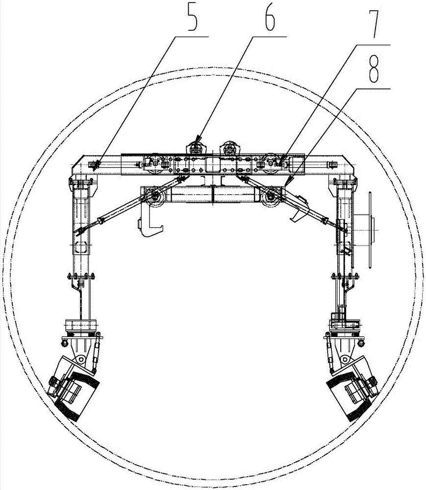
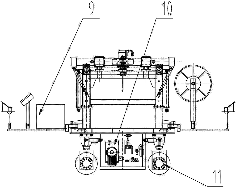
[0045] Such as Figure 1-2 As shown, the present embodiment provides a tire-type subway pavement machine, which includes a gantry structure 5, a lifting structure 6, a variable span structure 7, a multifunctional spreader 8, an electrical system / 9, a hydraulic system 10, the above-mentioned Walking device 11, the gantry structure includes a main beam and column structures installed on both sides of the main beam, the column structure is at least a secondary telescopic structure, the main beam is at least a secondary telescopic structure, the lifting The structure is installed on the main beam, and the outrigger structure is also configured on the column structure.

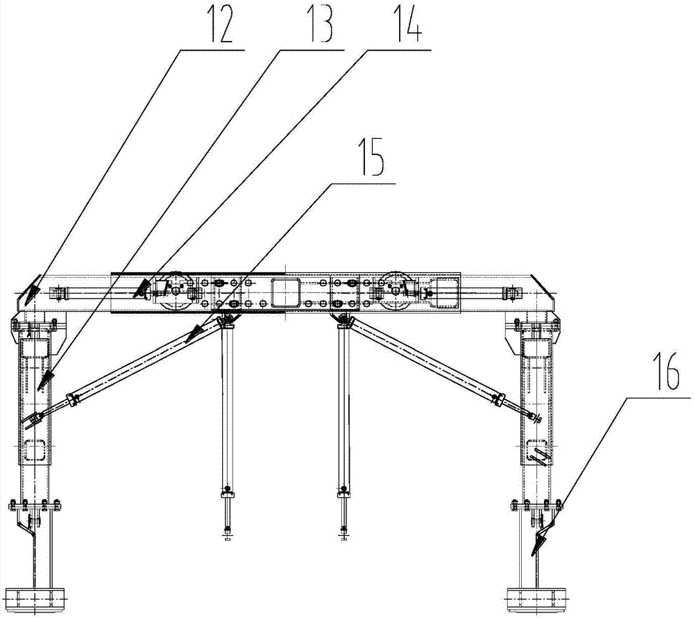
[0046] Such as Figure 3-5 As shown, the gantry structure is mainly composed of one set of main beam 12, two sets of column structures 13, four traversing oil cylinders 14, two sets of turning legs 16, and fou...


PUM


Abstract

The invention discloses a tire type metro replaced laying machine and a span changing method thereof. The tire type metro replaced laying machine comprises a portal structure, a lifting structure, a span changing structure, an electrical system, a hydraulic system and a walking device. The walking device comprises a supporting frame. Walking mechanisms are arranged on the two sides of the supporting frame, and each walking mechanism comprises a walking frame and a walking wheel set. Wheel faces of each walking wheel set comprise a cylindrical wheel face and a conical wheel face connected withthe cylindrical wheel face, wherein the outer diameters of the conical wheel face are large inside and small outside. The span changing mechanism is further arranged and used for realizing span changing. According to the tire type metro replaced laying machine, the temporary track laying process of metro track laying is reduced through the walking device, the cost input is reduced, the construction period is ensured, the walking device rotates by 0-45 degrees in the circuit direction to adapt to walking on different-radius pipe walls, and the limiting requirements for special conditions of small curves, station platforms and civil air defense doors can be met.

Description

technical field [0001] The invention relates to the technical field of subway tunnel construction, in particular to a tire-type subway paving machine and a method for changing the span. Background technique [0002] At present, with the rapid development of urban infrastructure, more and more cities have begun to vigorously build subway rail transit. Due to the limitation of shield size, the construction space in the subway is narrow. In the process of subway construction, subway track laying is the most important At the same time, it is also a part of the larger workload. Often the efficiency of subway track laying directly affects the timing of the opening of the subway. The traditional subway track laying mainly adopts the "replacement method", that is, during the construction, the first section of the track is manually laid for the rail flat car to transport the rail row and other components; then it is manually laid on both sides of the curved surface and the plane of t...

Claims


Application Information

Patent Timeline
Patent Type & Authority Applications(China)
IPC IPC(8): E01B29/02B66C9/08B66C5/02B66C6/00
CPCB66C5/02B66C6/00B66C9/08E01B29/02
Inventor 刘中玲董平华张雄超尹桂芳张尚尉胡进孙连佳胡浩蔡苠升蔡兴
Owner CHINA RAILWAY HEAVY MACHINERY
Why Eureka
Try Eureka