Construction Technology of Hydraulic Synchronous Lifting and Installation of Steel Truss Corridor

A technology of hydraulic synchronous lifting and construction technology, applied in the processing of building materials, construction, building structure, etc., can solve the problems of affecting the efficiency of installation, incapable of cross operation, taking a long time, etc., to achieve high construction efficiency, guarantee The effect of high installation period and construction safety

Active Publication Date: 2019-11-12
NO 3 ENG CO LTD OF CCCC THIRD HARBOR ENG CO LTD
View PDF6 Cites 0 Cited by
  • Summary
  • Abstract
  • Description
  • Claims
  • Application Information

AI Technical Summary

Problems solved by technology

[0002] like image 3 As shown, the enterprise needs a transportation corridor. One end of the transportation corridor is in the water, and the other end is on the shore. The two ends are respectively connected to No. 0 and No. 1 coal transfer stations. The total length is 469.16m. The slope of the transportation corridor is mainly composed of foundation parts (cast-in-place piles and cast-in-place piers), the upper part is composed of cast-in-place concrete frame columns and steel truss structure corridor installation, and the single-span horizontal projection length is between 29.5-34.7m Each span is 50*50cm cast-in-place frame column as the support of the corridor. The weight of each span of the steel structure truss corridor is about 76t, and the location of the corridor is generally high, with the highest point reaching 63m. If a super large crane is used during installation, The shoal on the shore is relatively soft, and the super-large crane will sink in during the hoisting process. Before work, the shoal must be solidified and hardened in a large area and deep. Fixed in place, the rental of super-large cranes is calculated on a shift basis, the cost is high, the floor area is large, and cross operations cannot be performed, which affects the efficiency of installation

Method used


Image

  • Construction Technology of Hydraulic Synchronous Lifting and Installation of Steel Truss Corridor
  • Construction Technology of Hydraulic Synchronous Lifting and Installation of Steel Truss Corridor
  • Construction Technology of Hydraulic Synchronous Lifting and Installation of Steel Truss Corridor

Examples


Embodiment Construction

[0046] The present invention will be further explained below in conjunction with the accompanying drawings and specific embodiments. It should be understood that the following specific embodiments are only used to illustrate the present invention and are not intended to limit the scope of the present invention.

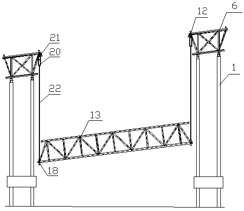
[0047] The hydraulic synchronous lifting installation construction technology of the steel truss corridor according to the present invention comprises the following steps:

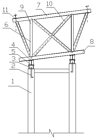
[0048] (1) Install the embedded part 2 on the top of the column 1;

[0049] (2) Laying out the top of the column;

[0050] (3) Install the hinge support: hoist the hinge support 3 to the top of the column 1, align it with the installation axis, check the elevation again after positioning, and install the hinge support after confirming that it meets the requirements. The support 3 is reliably welded to the embedded part 2 on the top of the column;

[0051] (4) Positioning control of the installat...


PUM


Abstract

The invention discloses a hydraulic synchronous lifting mounting construction technology of a steel truss corridor. During construction, firstly, a foundation corridor is fixed at the upper portion ofvertical columns and mounted in place according to the designed angle, a middle cross corridor is manufactured between the two vertical columns on site, lifting hoisting points and lower hoisting points are set, and four hydraulic lifters are utilized to synchronously hoist the middle cross corridor; corridor steel structures of the technology are spliced on the ground; and each cross corridor steel structure is lifted in place at a time, the construction efficiency is high, safety is improved, through lifting and hoisting of the foundation corridor, the lifting operation time is short, the high-attitude operation quantity is reduced to the least, the construction period is shortened, the cost is reduced, the maneuverability is high, mounting and dismounting are convenient, the mounting precision reaches the millimeter level, the precision is high, the effect is good, and the hydraulic synchronous lifting mounting construction technology is worth popularizing.

Description

technical field [0001] The invention belongs to the field of lifting construction technology for super-large steel structures, and in particular relates to a hydraulic synchronous lifting installation construction technology for steel truss corridors. Background technique [0002] like image 3 As shown, the enterprise needs a transportation corridor. One end of the transportation corridor is in the water, and the other end is on the shore. The two ends are respectively connected to No. 0 and No. 1 coal transfer stations. The total length is 469.16m. The slope of the transportation corridor is mainly composed of foundation parts (cast-in-place piles and cast-in-place piers), the upper part is composed of cast-in-place concrete frame columns and steel truss structure corridor installation, and the single-span horizontal projection length is between 29.5-34.7m Each span is 50*50cm cast-in-place frame column as the support of the corridor. The weight of each span of the steel s...

Claims


Application Information

Patent Timeline
Patent Type & Authority Patents(China)
IPC IPC(8): E04G21/14E04G21/16
CPCE04G21/14E04G21/16E04G21/163
Inventor 蒋建荣曹久慧刘蒂吴维莉俞仲明
Owner NO 3 ENG CO LTD OF CCCC THIRD HARBOR ENG CO LTD
Why Eureka
Try Eureka