High-precision fiber-optic gyroscope optical path structure with function of suppressing relative strength noise

A relative intensity noise, fiber optic gyroscope technology, applied in Sagnac effect gyroscopes, gyroscopes/steering sensing devices, instruments, etc., can solve the problems of random walk coefficients that cannot be reduced, limited applications, and difficult debugging. , to increase the design difficulty and gyro debugging difficulty, suppress relative intensity noise, and achieve the effect of simple and effective method

Inactive Publication Date: 2018-05-04
TIANJIN NAVIGATION INSTR RES INST
View PDF3 Cites 8 Cited by
  • Summary
  • Abstract
  • Description
  • Claims
  • Application Information

AI Technical Summary

Problems solved by technology

However, as the power increases, the relative intensity noise of the light source replaces the shot noise and gradually becomes the main noise source of the gyroscope, which limits the improvement of the signal-to-noise ratio (and accuracy) of the gyroscope by increasing the optical power, and the random walk coefficient cannot be reduced.
[0011] Therefore, the suppression of relative intensity noise has become the key to the further improvement of gyroscope accuracy. Some RIN suppression technologies have be

Method used


Image

  • High-precision fiber-optic gyroscope optical path structure with function of suppressing relative strength noise
  • High-precision fiber-optic gyroscope optical path structure with function of suppressing relative strength noise
  • High-precision fiber-optic gyroscope optical path structure with function of suppressing relative strength noise

Examples


Embodiment Construction

[0024] Embodiments of the present invention will be described in further detail below in conjunction with the accompanying drawings.

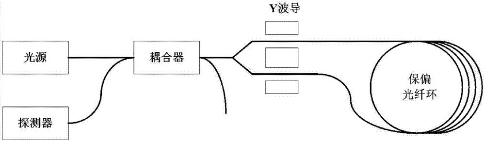
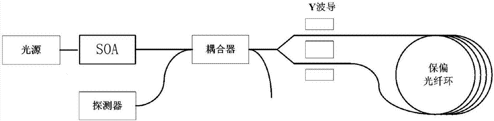
[0025] A high-precision fiber optic gyroscope optical path structure with the function of suppressing relative intensity noise, such as figure 2 As shown, it includes an ASE light source, a detector, a semiconductor optical amplifier (SOA), a Y waveguide integrated optical device, a coupler and a polarization-maintaining fiber ring, and the semiconductor optical amplifier (SOA) is arranged between the ASE light source and the coupler, and the ASE The light source is amplified by the semiconductor optical amplifier (SOA) to the coupler and then divided into two paths through the Y-waveguide integrated optical device to enter the polarization-maintaining fiber ring. The interference light from the polarization-maintaining fiber ring passes through the coupler and then enters the detector. The optical path structure of this high-precision fiber o...


PUM


Abstract

The invention relates to a high-precision fiber-optic gyroscope optical path structure with a function of suppressing relative strength noise. The high-precision fiber-optic gyroscope optical path structure comprises an ASE (Amplified Spontaneous Emission) light source, a detector, a coupler, a Y waveguide integrated optical device and a polarization-maintaining optical fiber ring. The high-precision fiber-optic gyroscope optical path structure is mainly and technically characterized in that a semiconductor optical amplifier is arranged between the ASE light source and the coupler; the ASE light source passes through the semiconductor optical amplifier, the coupler and the Y waveguide integrated optical device and is then divided into two paths which enter the polarization-maintaining optical fiber ring; interference light from the polarization-maintaining optical fiber ring passes through the coupler and then enters the detector. According to the high-precision fiber-optic gyroscope optical path structure disclosed by the invention, the semiconductor optical amplifier (SOA) working in a saturation region is added in a fiber-optic gyroscope optical path; and noises are suppressed by using optical characteristics of the SOA, so that relative strength noise of the light source is effectively inhibited and the precision of a fiber-optic gyroscope is improved; meanwhile, the SOA isadopted and an extra noise suppression channel and a feedback loop do not need to be added, so that design difficulty of a demodulation circuit and debugging difficulty of the gyroscope are preventedfrom being increased; a realization method of the high-precision fiber-optic gyroscope optical path structure is simple and effective.

Description

technical field [0001] The invention belongs to the technical field of fiber optic gyro, in particular to a high-precision fiber optic gyro optical path structure with the function of suppressing relative intensity noise. Background technique [0002] White noise in fiber optic gyroscopes can be characterized by random walk coefficients. For ultra-high-precision fiber optic gyroscopes, the accuracy requirements are very strict, and the random walk coefficient requirements are less than one ten thousandth. Optical path, circuit system noise and drift are the main factors that limit the development of precision. In order to develop ultra-high-precision fiber optic gyroscopes, the circuit and optical path noise of fiber optic gyroscopes must be reduced to a minimum. With the advancement of circuit device performance and modulation and demodulation schemes, circuit noise is no longer the main factor limiting the development of fiber optic gyroscopes to higher precision, but the ...

Claims


Application Information

Patent Timeline
IPC IPC(8): G01C19/72
CPCG01C19/721
Inventor 陈馨张贵材林毅马骏张书颖左文龙
Owner TIANJIN NAVIGATION INSTR RES INST
Why Eureka
Try Eureka