
Lens driving device, camera module, and manufacturing method of lens driving device

A technology of a lens drive device and a manufacturing method, which is applied in the direction of electromechanical devices, manufacturing of motor generators, installation, etc., can solve the problem of difficulty in ensuring the joint strength between the end of the coil and the leaf spring, hindering the thinning of the thickness dimension, and the inability to increase the number of solder joints. Material volume and other issues, to achieve the effect of reducing the number of turns, reducing the height dimension, and improving the conductivity

Active Publication Date: 2020-07-17
ALPS ALPINE CO LTD
View PDF1 Cites 0 Cited by
  • Summary
  • Abstract
  • Description
  • Claims
  • Application Information

AI Technical Summary

Problems solved by technology

As a result, the height dimension of the protruding portion protruding from the outer surface of the leaf spring becomes large, which prevents the thickness dimension of the lens driving member from being thinned in the optical axis direction.
[0010] In addition, if the solder is mainly provided only on the outer surface of the leaf spring, the amount of solder that contributes to the joining of the coil end and the leaf spring cannot be increased, and it is difficult to ensure sufficient bonding strength between the coil end and the leaf spring.

Method used


Image

  • Lens driving device, camera module, and manufacturing method of lens driving device
  • Lens driving device, camera module, and manufacturing method of lens driving device
  • Lens driving device, camera module, and manufacturing method of lens driving device

Examples


Embodiment Construction

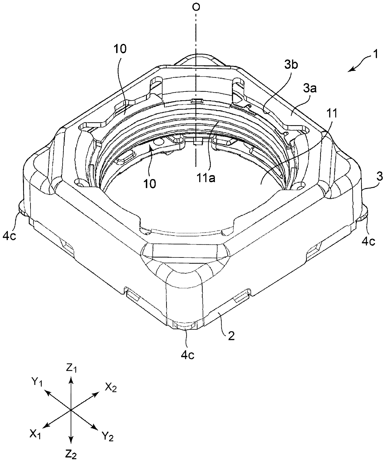
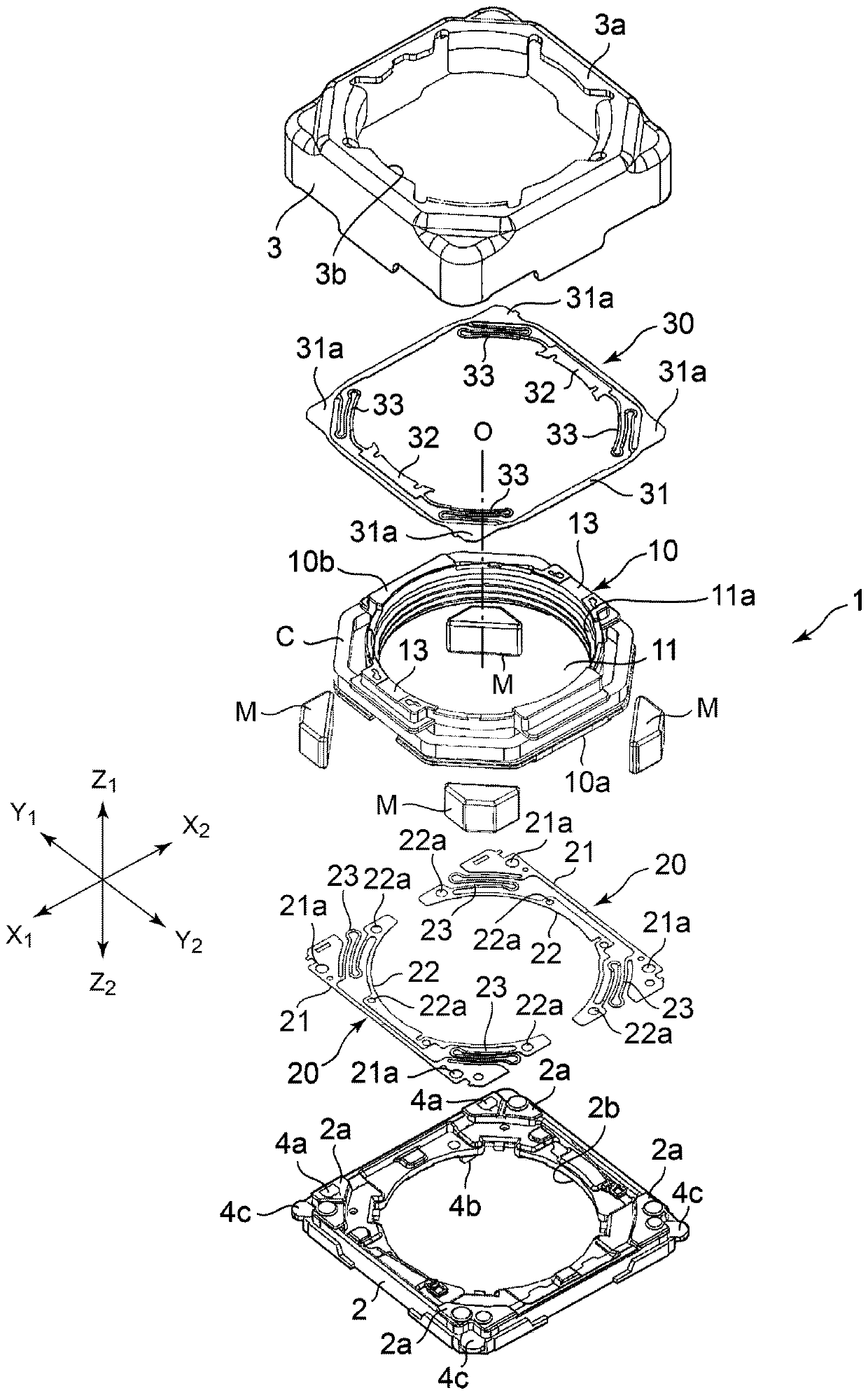
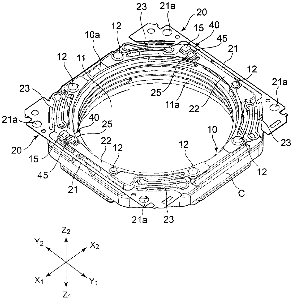
[0067] exist figure 1 and figure 2 The overall structure of the lens driving device 1 according to the embodiment of the present invention is shown in .

[0068] The lens driving device 1 has a moving member 10 . The moving member 10 is a cylindrical lens holding member. A lens body (lens barrel or lens barrel) is installed in the center hole 11 of the moving member 10 . The lens body includes a lens group composed of one lens or a plurality of lenses, and a lens holder holding the lens or the lens group. A female thread portion 11 a is formed in the center hole 11 , and a male thread portion is formed on the outer peripheral surface of the lens holder. By screwing the male thread portion and the female thread portion 11 a together, the lens body is attached and mounted on the moving member 10 . It should be noted that the lens body may also be fixed to the moving member 10 by an adhesive.

[0069] figure 1 and figure 2 The Z1-Z2 direction in is the up-down direction,...


PUM


Abstract

The invention provides a lens driving device capable of reliably connecting a leaf spring supporting a moving member and a coil provided to the moving member and realizing thinning of the moving member, a camera module using the lens driving device, and a manufacturing method of the lens driving device. A protruding portion (15) is provided on a moving member (10) holding a lens body, and a tail end portion (41a) of a coated conductor (41) constituting a coil is wound around the protruding portion (15) to form a wire winding portion (42). A joining edge portion (27) of a brazing portion (25) formed on a movable side support piece (22) of a lower leaf spring (20) faces the wire winding portion (42). A communicating portion (28) is formed in the brazing portion (25). Therefore, the solder can be adhered to an inner surface (20a) and an outer surface (20b) of the lower leaf spring (20) and the wire winding portion (42).

Description

technical field [0001] The present invention relates to a lens driving device, a camera module using the lens driving device, and a method of manufacturing the lens driving device in which a coil provided on a moving member on which a lens body is mounted and a device supporting the moving member are brazed. leaf spring. Background technique [0002] Patent Document 1 describes an invention related to a lens driving device. [0003] This lens driving device has a lens holding member (moving member) and a supporting member capable of mounting a lens body. The lens holding member is supported by the supporting member via a lower leaf spring and an upper leaf spring. A coil is provided on the lens holding member, and a magnet is fixed on the supporting member side. A connection terminal portion is formed on the metal member embedded in the supporting member, and a driving current is applied to the coil from the connection terminal portion via the lower plate spring to move t...

Claims


Application Information

Patent Timeline
Patent Type & Authority Patents(China)
IPC IPC(8): G02B7/09H02K41/035H02K15/00
CPCG02B7/09H02K15/00H02K41/0356
Inventor 长田宽志
Owner ALPS ALPINE CO LTD
Learn More