
0db Power Backoff Common Mode Amplitude Modulator and Quadrature Amplitude Modulation Transmitter

An amplitude modulation and power back-off technology, applied in amplitude modulation components, modulated carrier systems, digital transmission systems, etc., and can solve the problems of reduced power added efficiency and power amplifier gain.

Active Publication Date: 2020-12-22
郭海燕
View PDF7 Cites 0 Cited by
  • Summary
  • Abstract
  • Description
  • Claims
  • Application Information

AI Technical Summary

Problems solved by technology

2. The power amplifier has saturated output power. When the output power of the amplifier is close to its saturated output power, the gain of the power amplifier will gradually decrease (that is, the output power varies nonlinearly with the input power)
Therefore, when the output power is reduced, the power added efficiency will be reduced

Method used


Image

  • 0db Power Backoff Common Mode Amplitude Modulator and Quadrature Amplitude Modulation Transmitter
  • 0db Power Backoff Common Mode Amplitude Modulator and Quadrature Amplitude Modulation Transmitter
  • 0db Power Backoff Common Mode Amplitude Modulator and Quadrature Amplitude Modulation Transmitter

Examples


Embodiment Construction

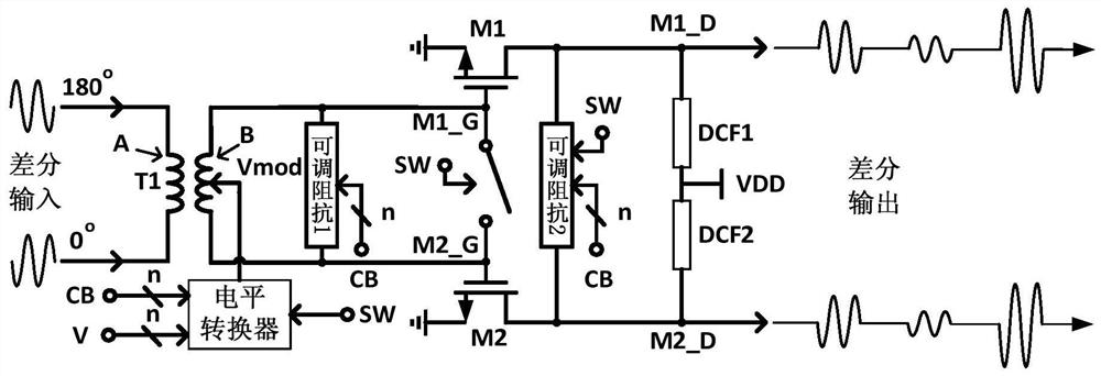
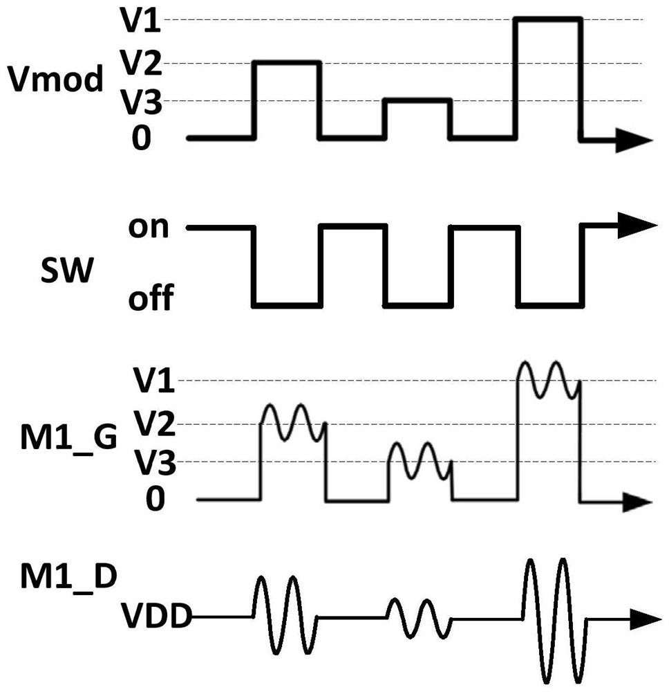
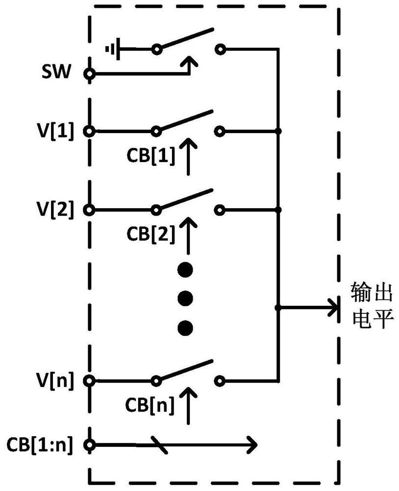
[0073] Such as figure 1As shown, the present invention provides a 0dB power backoff common mode amplitude modulator. Wherein, the transistors M1 and M2 have the same structure and size, and the gates of the transistors M1 and M2 are connected to an electric control switch, and the turn-on and turn-off of the electric control switch is controlled by the potential of the node SW. The gates of the transistor M1 and the transistor M2 are respectively connected to the two ends of the B coil in the transformer T1. The center tap of the B coil in the transformer T1 is the node Vmod, which is connected to the output terminal of the level shifter, and the amplitude modulation signal is input from this node to dynamically control the gate levels of the transistor M1 and the transistor M2.

[0074] The two ends of the A coil in the transformer T1 are connected to the differential input terminal, and the sine signal of the differential carrier frequency will be input from this terminal....


PUM


Abstract

The invention relates to a quadrature amplitude modulation transmitter which comprises four 0dB power back-off common mode amplitude modulators. Carrier sinusoidal signals with phases of 0, 180, 90 and 270 degrees are input by the four 0dB power back-off common mode amplitude modulators, wherein amplitudes of the carrier sinusoidal signals are the same. The sinusoidal signals with differential carrier frequencies are applied to a first coil of an inductor or a transformer, a single-end carrier signal is applied to the first coil. An amplitude modulation signal is received at a position of a centre tap of the inductor or a second coil, thereby dynamically controlling gate levels of two transistors. The position of the centre tap is a virtual site of the differential signals and the amplitude of a carrier frequency signal is 0, so when any circuit is connected at the position, the carrier frequency signal is not attenuated by a load of the circuit. Drains of the two transistors output amplitude modulated modulation signals. According to the quadrature amplitude modulation transmitter and the 0dB power back-off common mode amplitude modulator, the amplitude modulator and a power amplifier can be effectively combined, and under the condition of ensuring the maximum power addition efficiency, the amplitude modulation of the output power is realized by dynamically changing the gain and saturation output power of the power amplifier.

Description

technical field [0001] The invention relates to radio frequency wireless communication technology, in particular to a 0dB power backoff common-mode amplitude modulator, a quadrature amplitude modulation transmitter and a quadrature amplitude modulation signal synthesis method. Background technique [0002] The system block diagram of a traditional quadrature amplitude modulation transmitter is shown in Figure 15 shown. The quadrature amplitude modulation signal is generated by the quadrature amplitude modulator, the quadrature amplitude modulation signal includes QPSK, 16QAM, 64QAM,...,4 i QAM (i is an integer greater than or equal to 1). The quadrature amplitude modulation signal is input to the power amplifier to amplify the signal amplitude. The amplitude-amplified quadrature amplitude modulation signal is input to the band-pass filter to filter out-of-band signal energy. Finally, the quadrature amplitude modulation signal is radiated and output through the antenna. ...

Claims


Application Information

Patent Timeline
IPC IPC(8): H04L27/36H03C1/06
CPCH03C1/06H04L27/362
Inventor 郭海燕
Owner 郭海燕
Learn More