High-efficiency oil tube machining device

A processing device and high-efficiency technology, applied in positioning devices, metal processing equipment, metal processing machinery parts, etc., can solve the problems of poor effect and low efficiency, and achieve high efficiency, good effect and good processing effect

Inactive Publication Date: 2018-05-08
全椒县新华机械有限责任公司
View PDF6 Cites 4 Cited by
  • Summary
  • Abstract
  • Description
  • Claims
  • Application Information

AI Technical Summary

Problems solved by technology

[0003] During the processing of the oil pipe, it needs to be drilled. The existing equipment has low efficiency and poor effect, and needs further improvement.

Method used


Image

  • High-efficiency oil tube machining device

Examples


Embodiment Construction

[0021] It should be noted that the embodiments of the present application and the features in the embodiments can be combined with each other if there is no conflict; the following describes the present invention in detail with reference to the drawings and the embodiments.

[0022] Reference figure 1 :

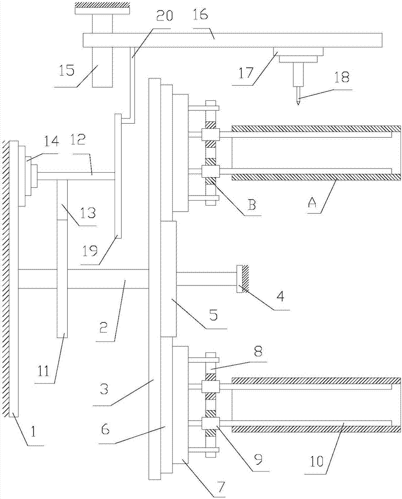
[0023] A high-efficiency tubing processing device proposed by the present invention includes a bracket 1, a supporting shaft 2, a driving mechanism, a supporting plate 3, a fixing frame 4, a driving gear 5, a plurality of clamping parts, and a drilling part.

[0024] The support shaft 2 is rotatably connected with the bracket 1; the driving mechanism is used to drive the support shaft 2 to rotate; the support plate 3 is installed on the support shaft 2.

[0025] The driving gear 5 is located on the side of the supporting plate 3 away from the supporting shaft 2. The driving gear 5 is connected to the fixing frame 4, and the center line of the driving gear 5 coincides with the axis of...


PUM


Abstract

The invention discloses a high-efficiency oil tube machining device which comprises a support, a supporting shaft, a drive mechanism, a supporting plate, a fixed frame, a driving gear, multiple clamping portions and a drilling portion. The supporting shaft is rotationally connected with the support. The drive mechanism is used for driving the supporting shaft to rotate. The supporting plate is mounted on the supporting shaft. The driving gear is located on the side, away from the supporting shaft, of the supporting plate and is connected with the fixed frame, and the center line of the drivinggear coincides with the axis of the supporting shaft. The multiple clamping portions surround the periphery of the driving gear, each clamping portion comprises a driven gear and a clamping unit, andthe driven gears are rotationally mounted on the supporting plate and are engaged with the driving gear. The clamping units are connected with the driven gears and used for clamping oil tubes. The drilling portion is used for carrying out drilling machining on the oil tubes.

Description

Technical field [0001] The invention relates to the technical field of oil pipe processing, in particular to a high-efficiency oil pipe processing device. Background technique [0002] An oil extraction machine is a kind of machinery and equipment used to extract oil, commonly known as a "kowtow machine". The oil is pumped out of the well by means of pressure. When the pumping unit is upstroke, the tubing elastically contracts and moves upwards, which drives the mechanical unblocking oil extractor to move upwards, hitting the sliding sleeve to generate vibration; at the same time, the positive check valve is closed, and the variable-diameter piston assembly blocks oil when the pumping unit is under During the stroke, the tubing elastically stretches and moves downwards, driving the mechanical plug-removing oil extractor to move downwards, hitting the sliding sleeve to generate vibration; at the same time, the reverse check valve is partially closed, and the reducing piston assemb...

Claims


Application Information

Patent Timeline
Patent Type & Authority Applications(China)
IPC IPC(8): B23B41/00B23Q1/26B23Q1/52B23Q3/06
CPCB23B41/00B23Q1/26B23Q1/522B23Q3/064
Inventor 王臣
Owner 全椒县新华机械有限责任公司
Why Eureka
Try Eureka