Heavy oil hydrogenation method to improve catalyst utilization

A heavy oil hydrogenation and catalyst technology, which is applied in the fields of hydrogenation treatment process, hydrocarbon oil treatment, petroleum industry, etc., and can solve the problem that the operating cycle of the device is not greatly improved.

Active Publication Date: 2020-10-16
CHINA PETROLEUM & CHEM CORP +1
View PDF7 Cites 0 Cited by
  • Summary
  • Abstract
  • Description
  • Claims
  • Application Information

AI Technical Summary

Problems solved by technology

However, this method does not greatly increase the operating cycle of the device.

Method used


Image

  • Heavy oil hydrogenation method to improve catalyst utilization
  • Heavy oil hydrogenation method to improve catalyst utilization
  • Heavy oil hydrogenation method to improve catalyst utilization

Examples


Embodiment 1

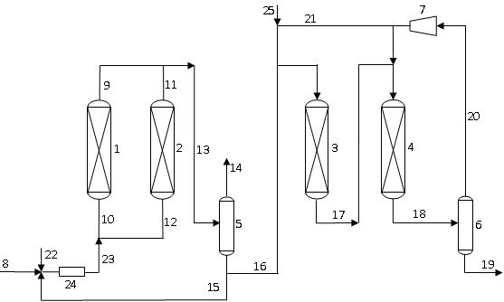
[0067] according to figure 1 In the process flow, the hydrogenation pretreatment reaction zone includes a switchable first hydrogenation pretreatment reaction zone and a second hydrogenation pretreatment reaction zone, the first hydrogenation pretreatment reaction zone is provided with a reactor 1, and the second hydrogenation pretreatment reaction zone is provided with a reactor 1. A reactor 2 is arranged in the second hydrogenation pretreatment reaction zone, and the hydrogenation treatment reaction zone includes a reactor 3 and a reactor 4 arranged in series. According to the material flow direction, the reactor in the hydrogenation pretreatment reaction zone (only one hydrogenation pretreatment reaction zone is online during operation) is filled with catalyst A, catalyst B and catalyst C, and the loading volume ratio of each catalyst is 2:7 : 1. Catalyst B and Catalyst C are installed in the reactor 3 of the hydrotreating reaction zone, and the loading volume ratio of the...

Embodiment 2

[0073] according to figure 1 In the described process flow, only one hydrogenation pretreatment reaction zone is set, and a reactor 1 is set in this hydrogenation pretreatment reaction zone, and the hydrogenation treatment reaction zone includes reactor 3 and reactor 4 arranged in series, and adding The catalyst loading in the hydrogen pretreatment reaction zone accounts for 36% of the total catalyst loading in the device. According to the material flow direction, catalyst A, catalyst B and catalyst C are loaded in the reactor 1 of the hydrogenation pretreatment reaction zone, and the loading volume ratio of the three catalysts is 2:6:2. Catalyst B and catalyst C are housed in hydrotreating reaction zone reactor 3, and the loading volume ratio of two kinds of catalysts is 3: 7, and catalyst C and catalyst D are filled in reactor 4, and the loading volume ratio of two kinds of catalysts is 3: 7. The conditions and test results of reactor hydrotreating are listed in Table 2.

...

Embodiment 3

[0079] according to figure 1 In the process flow, the hydrogenation pretreatment reaction zone includes a switchable first hydrogenation pretreatment reaction zone and a second hydrogenation pretreatment reaction zone, the first hydrogenation pretreatment reaction zone is provided with a reactor 1, and the second hydrogenation pretreatment reaction zone is provided with a reactor 1. A reactor 2 is arranged in the second hydrogenation pretreatment reaction zone, and the hydrogenation treatment reaction zone includes a reactor 3 and a reactor 4 arranged in series. According to the material flow direction, the reactor in the hydrogenation pretreatment reaction zone (only one hydrogenation pretreatment reaction zone is online during operation) is filled with catalyst A, catalyst B and catalyst C, and the loading volume ratio of each catalyst is 3:6 : 1. Catalyst B and catalyst C are housed in hydrotreating reaction zone reactor 3, and the loading volume ratio of two kinds of cata...


PUM

PropertyMeasurementUnit
specific surface areaaaaaaaaaaa

Abstract

The invention discloses a heavy oil hydrogenation method capable of improving a utilization ratio of a catalyst. According to the method, after hydrogen is saturatedly dissolved in raw heavy oil, hydrodemetallization and partial desulfurization reactions occur in a hydrogenation pretreatment zone, and the reaction effluent and hydrogen gas enter a hydrogenation treatment reaction zone and undergohydrodesulfurization and hydrodenitrogenation reactions, wherein the reaction temperature in the hydrogenation pretreatment zone is higher than that of the hydrogenation treatment reaction zone. Through a reaction at a higher temperature in the hydrogenation pretreatment zone, the most of metal impurities in the materials are removed so that the inactivation reason of the desulfurization catalystand / or the denitrification catalyst in the hydrogenation pretreatment reaction zone is changed from metal deposition and coking inactivation into only coking inactivation and the desulfurization catalyst and the denitrification catalyst can be regenerated after one use cycle and thus the operation cycle of the hydrogenation device is prolonged, device operating efficiency is improved and economicefficiency is improved.

Description

technical field [0001] The invention relates to the field of petroleum refining, in particular to a heavy oil hydrogenation method for improving catalyst utilization. Background technique [0002] At present, the demand for light and medium oil products in the domestic and foreign oil product markets will continue to rise, while the demand for heavy oil products such as fuel oil will show a downward trend. In addition, due to the increasing pressure of environmental protection, countries have generally raised the quality standard requirements of petroleum products, especially gasoline and diesel products for vehicles. Under the above-mentioned market trend, the refining technology that can not only realize the lightening of heavy oil at a more economical and reasonable price, but also make the obtained products meet the increasingly stringent specifications of gasoline and diesel products has become a key technology developed by domestic and foreign refining technology devel...

Claims


Application Information

Patent Timeline
Patent Type & Authority Patents(China)
IPC IPC(8): C10G65/04
CPCC10G65/04C10G2300/107C10G2300/1077C10G2300/202C10G2300/205C10G2300/206
Inventor 吴锐韩照明刘涛张彦杰葛培忠王军唐军孙庭阁王志勇
Owner CHINA PETROLEUM & CHEM CORP
Why Eureka
Try Eureka