Sound damping device and engine unit

A technology of muffler and muffler pipe, which is applied in the direction of muffler, engine components, machines/engines, etc. It can solve the problems of small air resistance, poor effect of medium and high frequency noise, increase installation workload, occupy space, etc., and achieve Strong adaptability, wide noise cancellation frequency, and good noise cancellation effect

Inactive Publication Date: 2018-05-08
SHAANXI JUZHEN POWER TECH CO LTD
View PDF4 Cites 0 Cited by
  • Summary
  • Abstract
  • Description
  • Claims
  • Application Information

AI Technical Summary

Problems solved by technology

[0003] The commonly used muffler is generally a resistant muffler with small air resistance, which mainly eliminates low-frequency noise in the engine exhaust, and has poor effect on medium and high-frequency noise. On the one hand, a large part of the exhaust system of high-power internal combustion engines has two exhaust outlets. If each exhaust outlet has a single muffler, it will have the disadvantages of increasing the installation workload and occupying space. The muffler does not meet the demand

Method used


Image

  • Sound damping device and engine unit
  • Sound damping device and engine unit
  • Sound damping device and engine unit

Examples


Embodiment 1

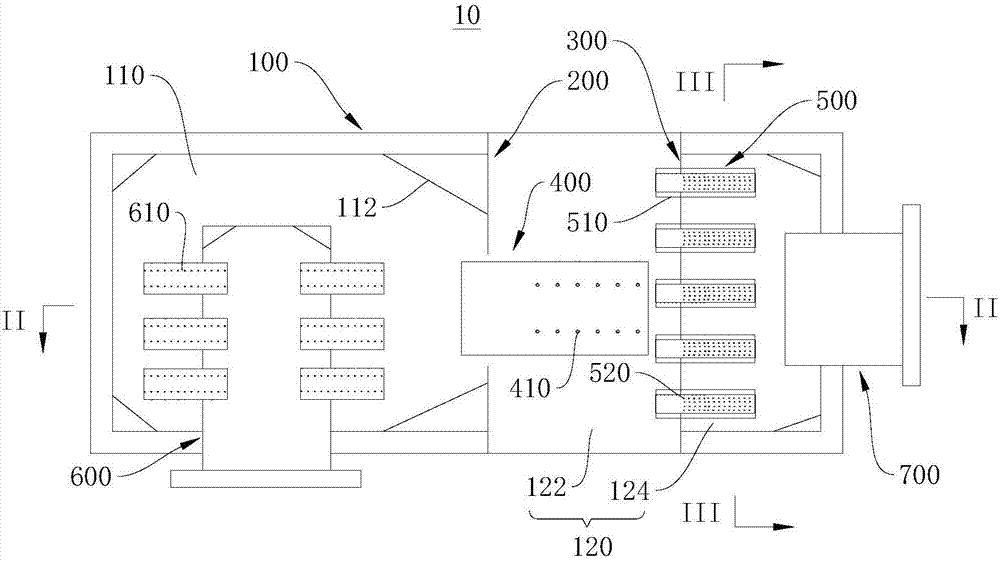
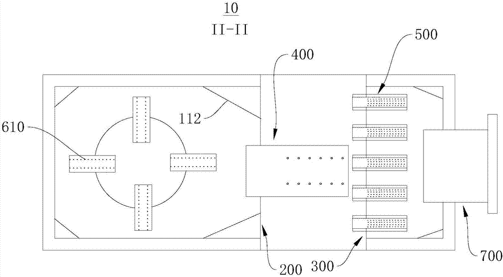
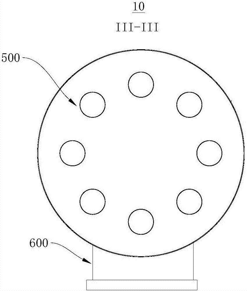
[0044] Please refer to Figure 1 to Figure 5 , this embodiment provides a muffler device 10, which includes a cylinder 100; a first partition 200, the first partition 200 divides the cylinder 100 into a first space 110 and a second space distributed radially along the cylinder 100. The space 120; the second partition 300, the second partition 300 divides the second partition 300 and the second space 120 into a first subspace 122 and a second subspace 124 radially distributed along the cylinder body 100; The acoustic tube 400, the first muffler tube 400 is provided with a plurality of first muffler holes 410 on the tube wall, the first muffler holes 410 communicate with the first space 110 and the first subspace 122; the second muffler tube 500, A plurality of second silencing holes 520 are opened on the pipe wall of the second silencing pipe 500, and the outer peripheral wall of the second silencing pipe 500 is covered with a silencing layer 510, and the second silencing holes...

Embodiment 2

[0058] The embodiment of the present invention also provides an engine set, the engine set includes the above-mentioned noise reduction device 10, and the noise reduction device 10 is installed on the engine body.

[0059] Since the engine set provided in the embodiment of the present invention includes the above-mentioned noise reduction device 10 , it also has the above-mentioned beneficial effects.


PUM


Abstract

The invention relates to the field of engine design, in particular to a sound damping device and an engine unit. The sound damping device is formed through combination of a resisting sound damping device formed by a first space and a second space, a resistance sound damping device formed by a sound damping layer, and a small hole sound damping device formed by a first sound damping hole and a second sound damping hole; the sound damping device has the sound damping function of the resistance sound damping device over noise in a intermediate frequency section or a high frequency section, and further has the sound damping function of the resisting sound damping device and the small hole sound damping device over noise in a intermediate frequency section or a low frequency section, and the sound damping frequency band is wide; and in the process of air flow passing the sound damping device, the noise is subjected to multiple times of sound damping of the first space, the second space, thesound damping layer, the first sound damping hole and the second sound damping hole, the sound damping effect is good, and the adaptability is high. The engine unit comprises the sound damping device, and further has the beneficial effects accordingly.

Description

technical field [0001] The invention relates to the field of engine design, in particular to a noise reduction device and an engine block. Background technique [0002] Among the noise sources of the exhaust system of the internal combustion engine, the exhaust noise is a high-temperature, high-speed pulsating airflow noise, which is the most energetic part of the engine noise and the most important component of the total engine noise. It is much higher than other noises such as other machine body mechanical noises and intake and exhaust noises. The noise reduction effect of the exhaust muffler directly affects the noise level of the entire unit. [0003] The commonly used muffler is generally a resistant muffler with small air resistance, which mainly eliminates low-frequency noise in the engine exhaust, and has poor effect on medium and high-frequency noise. On the one hand, a large part of the exhaust system of high-power internal combustion engines has two exhaust outle...

Claims


Application Information

Patent Timeline
Patent Type & Authority Applications(China)
IPC IPC(8): F01N1/10F01N13/14F01N13/16F01N3/00
CPCF01N1/10F01N1/082F01N3/005F01N13/14F01N13/16F01N2310/02
Inventor 白云龙
Owner SHAANXI JUZHEN POWER TECH CO LTD
Why Eureka
Try Eureka