Urea vortex mixer

A cyclone mixer and urea technology, applied in the direction of machine/engine, mechanical equipment, engine components, etc., can solve the problems of large back pressure and insufficient hydrolysis, and achieve low back pressure, improve conversion efficiency, and uniform urea atomization. Effect

Inactive Publication Date: 2018-05-08
无锡锡创汽车环保有限公司
View PDF5 Cites 8 Cited by
  • Summary
  • Abstract
  • Description
  • Claims
  • Application Information

AI Technical Summary

Problems solved by technology

[0003] The purpose of the present invention is to overcome the shortcomings of the above-mentioned mixer when it works, and solve the defects of large back pressure and insufficient hydrolysis under the compact layout.

Method used


Image

  • Urea vortex mixer

Examples


Embodiment Construction

[0024] The present invention will be further described below in conjunction with specific drawings and embodiments.

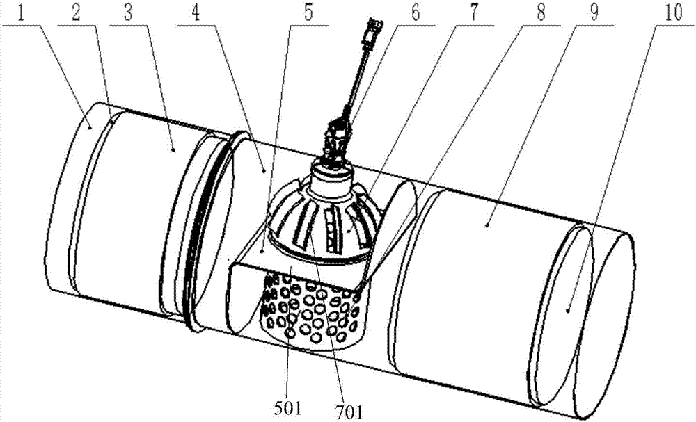
[0025] like figure 1 As shown, a urea cyclone mixer provided by the present invention includes a first cylinder 1, a first exhaust gas treatment carrier 2, a first liner 3, a second cylinder 4, a Z-shaped baffle 5, a nozzle 6, Hemispherical end cap 7, porous pipe 8, second liner 9, second tail gas treatment carrier 10;

[0026] In order to facilitate the assembly of the Z-shaped baffle plate 5, the hemispherical end cap 7, and the porous tube 8, the barrel of the mixer is welded by the first barrel 1 and the second barrel 4 with both ends open, and can be welded in the second barrel first. After the Z-shaped baffle 5, the hemispherical end cap 7, and the porous tube 8 are assembled in the cylinder 4, the first cylinder 1 and the second cylinder 4 are welded; wherein the Z-shaped baffle 5, the hemispherical end cap 7 , the porous pipe 8 is welded together;

...


PUM


Abstract

The invention provides a urea vortex mixer comprising a cylinder. The main improvement on the urea vortex mixer is that the two ends of the cylinder are both open, one end is used as an intake opening, and the other end is used an exhaust opening; a Z-shaped baffle is arranged in the cylinder, the inner cavity of the cylinder is divided into a front cavity and a back cavity, a vortex piece and a porous pipe are arranged in the cylinder, the vortex piece and the porous pipe are connected to the transverse portion of the Z-shaped baffle and communicate, the vortex piece is located in the front cavity of the cylinder, the porous pipe is located in the back cavity of the cylinder, the vortex piece is provided with vortex blades, the top end of the vortex piece is connected with a spray nozzle,the spray nozzle extends out from the circumference face of the cylinder, and the pipe wall of the porous pipe is provided with multiple air holes. The urea vortex mixer enables urea to be completelyhydrolyzed, the urea is not prone to crystallization, the backpressure is low, and the well-knit rhythm is achieved.

Description

technical field [0001] The invention relates to a urea swirl mixer, which is applied in a urea SCR system of an exhaust aftertreatment. Background technique [0002] At present, as the country pays more and more attention to environmental protection laws, and the diesel vehicle emission regulations of National IV and National V are gradually implemented, more and more attention is paid to the use of urea to reduce NOX after exhaust gas treatment, and urea can only be hydrolyzed into ammonia. It reacts with NOX, and the hydrolysis of urea is currently mainly realized through a mixer, but the mixer currently used is likely to generate a large back pressure, which affects the engine power; and the hydrolysis of urea is not sufficient; it cannot effectively reduce NOX, and is prone to crystallization . Contents of the invention [0003] The purpose of the present invention is to overcome the shortcomings of the above-mentioned mixer when it works, and solve the defects of lar...

Claims


Application Information

Patent Timeline
IPC IPC(8): F01N3/20F01N3/28
CPCF01N3/208F01N3/2896Y02T10/12
Inventor 袁可平王志春
Owner 无锡锡创汽车环保有限公司
Why Eureka
Try Eureka