Refueling check valve

A technology of one-way valve and valve body, which is applied in the direction of lifting valve, valve detail, control valve, etc., can solve the problems of no sealing ring on the closing surface of the refueling one-way valve, unable to prevent gas leakage, and complicated maintenance, so as to prevent fuel from surging , easy to replace, and improve the effect of sealing

Pending Publication Date: 2018-05-08
SAIC-GM-WULING AUTOMOBILE CO LTD
View PDF0 Cites 2 Cited by
  • Summary
  • Abstract
  • Description
  • Claims
  • Application Information

AI Technical Summary

Problems solved by technology

Some of the current refueling check valves are installed in the head of the refueling pipe of the fuel tank, which requires a larger fuel pipe head to ensure that the diameter of the pipeline after opening does not affect the fuel flow. At the same time, there is no sealing ring on the closing s

Method used


Image

  • Refueling check valve
  • Refueling check valve
  • Refueling check valve

Examples


Embodiment Construction

[0028] The specific embodiments of the present invention are given below in conjunction with the accompanying drawings, but the present invention is not limited to the following embodiments. Advantages and features of the present invention will be apparent from the following description and claims. It should be noted that all the drawings are in very simplified form and use imprecise ratios, which are only used for the purpose of conveniently and clearly assisting in describing the embodiments of the present invention.

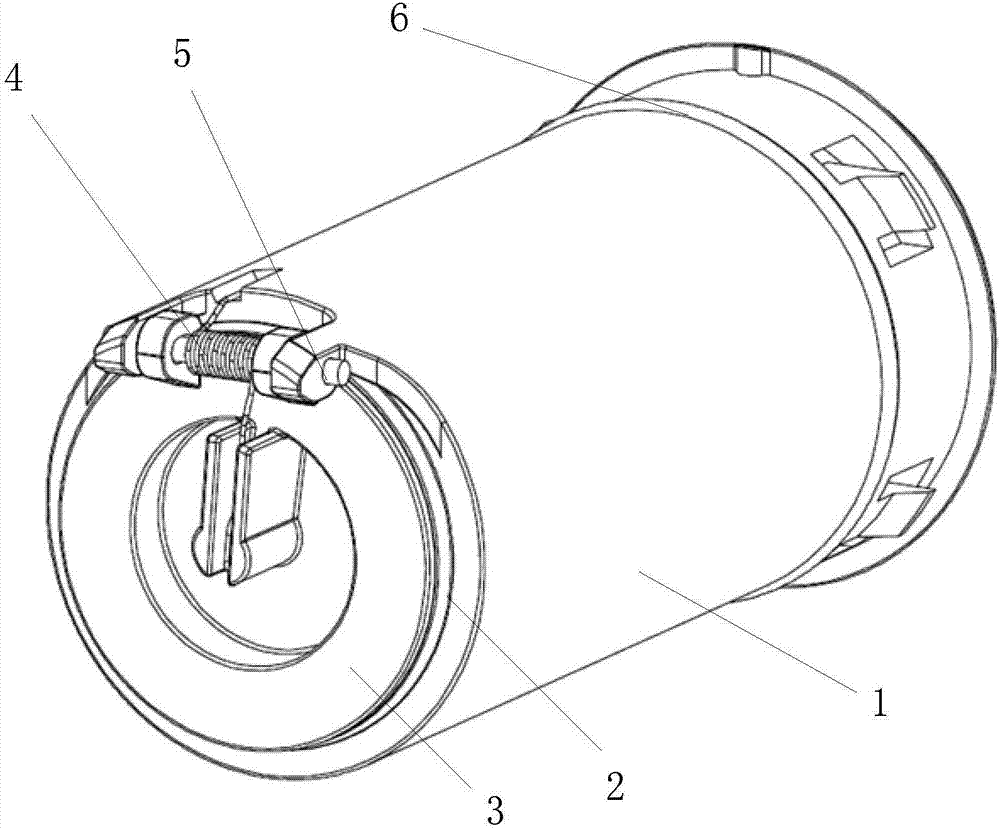
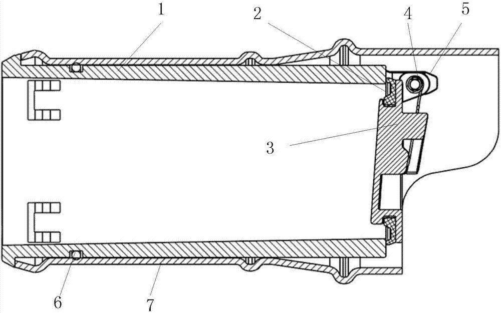
[0029] Please refer to figure 1 and figure 2 , figure 1 Shown is a schematic structural diagram of a refueling check valve in a preferred embodiment of the present invention, figure 2 Shown is a schematic diagram of the assembly and cooperation structure of the refueling check valve and the piping of the present invention. The present invention proposes a refueling check valve, comprising: a valve body 1; a valve plate 3, which is connected to the valve ...


PUM


Abstract

The invention discloses a refueling check valve. The refueling check valve comprises a valve body, a valve block and a rubber sealing pad, wherein the valve block is connected with the valve body through a rotary shaft pin; a spring is arranged on the rotary shaft pin; the spring is used for pre-tightening the valve block for realizing normal close of the valve; the rubber sealing pad is arrangedon the valve block in an interference fit manner and is arranged on a sealing match surface of the valve block and the valve body; a groove is formed in the outer side of the valve body; an O-shaped sealing ring is arranged in the groove for realizing sealing between the valve body and an outer side match pipe after assembly; the match pipe which is used for being matched with the valve body is provided with an extrusion bump on the outer part of the front end; a groove is formed in the match pipe; and an expansion section is arranged on the tail pipe diameter of the match pipe, so that different pipe diameters and match needs are met. By adopting the refueling check valve, rolling over of fuel can be effectively prevented; gas rolling over is prevented; rapid changing can be realized after damage; and meanwhile, the flow diameter of fuel in a pipeline is not affected after the valve block is opened.

Description

technical field [0001] The invention relates to the field of automobile fuel systems, and in particular to a refueling check valve. Background technique [0002] The automobile fuel supply system is composed of a refueling pipe, a fuel tank, a fuel pipeline and some valve bodies. The connection between the refueling pipe and the fuel tank is usually provided with a refueling check valve. Open it to prevent the fuel surge caused by the internal pressure of the fuel tank not being eliminated in time after the fuel filling is completed. Some of the current refueling check valves are installed in the head of the refueling pipe of the fuel tank, which requires a larger refueling pipe head to ensure that the diameter of the pipeline after opening does not affect the flow of fuel. Gas leaks. Some are installed on the inner side of the fuel tank of the fuel tank, and must be welded and assembled before the pipeline. After damage, they cannot be replaced, and the fuel tank must be ...

Claims


Application Information

Patent Timeline
IPC IPC(8): F16K15/03F16K27/02F16K1/46B60K15/077
CPCF16K15/033B60K15/077B60K2015/03269F16K1/46F16K27/0227
Inventor 唐基荣徐靖张允峰卓义盛徐雨玲
Owner SAIC-GM-WULING AUTOMOBILE CO LTD
Why Eureka
Try Eureka