Fiber bragg grating temperature measurement system of communication machine room, and communication machine room temperature detection method

A communication equipment room and fiber grating technology, applied in the field of temperature detection, can solve the problems of inability to obtain equipment through external measurement methods, difficult to measure hidden positions, and low measurement accuracy, so as to achieve no detection blind area, avoid electromagnetic interference, and calculate the amount of data. small effect

Inactive Publication Date: 2018-05-08
CHINA MOBILE GROUP DESIGN INST +1
View PDF13 Cites 5 Cited by
  • Summary
  • Abstract
  • Description
  • Claims
  • Application Information

AI Technical Summary

Problems solved by technology

However, for hidden positions inside the cabinet, there is still the problem that maintenance personnel cannot obtain the temperature of key points of the equipment through external measurement methods. It can be seen that this temperature measurement method has the disadvantages of poor real-time performance, difficulty in measuring hidden positions, and labor-intensive shortcomings.
Among them, the automatic temperature measurement method has low measurement accuracy because the automatic temperature acquisition equipment is easily interfered by equipment such as cabinets in the communication room

Method used


Image

  • Fiber bragg grating temperature measurement system of communication machine room, and communication machine room temperature detection method
  • Fiber bragg grating temperature measurement system of communication machine room, and communication machine room temperature detection method

Examples


Embodiment Construction

[0030] The following will clearly and completely describe the technical solutions in the embodiments of the present disclosure with reference to the accompanying drawings in the embodiments of the present disclosure. Obviously, the described embodiments are only some of the embodiments of the present invention, not all of them. Based on the embodiments in the present disclosure, all other embodiments obtained by persons of ordinary skill in the art without making creative efforts belong to the protection scope of the present disclosure.

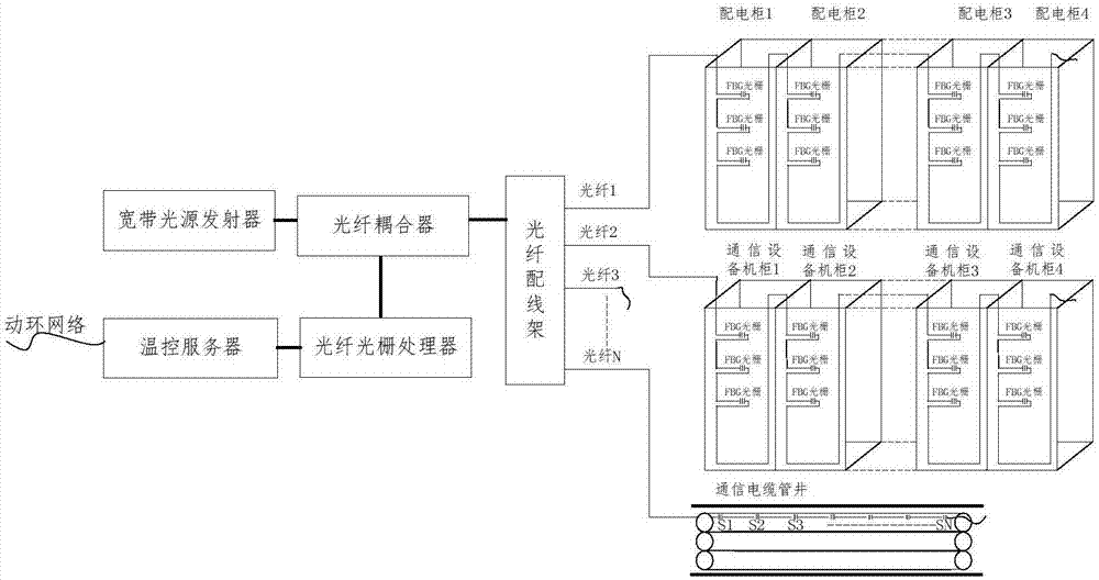
[0031] The invention provides a fiber grating temperature measuring system in a communication room, which can be applied to the temperature measurement work in the communication room. Such as figure 1 As shown, the system of the device includes a broadband light source transmitter, an optical fiber, a fiber Bragg grating sensor disposed on the optical fiber, and a fiber grating processor, wherein:

[0032] The broadband light source transmit...


PUM


Abstract

The present invention relates to a fiber bragg grating temperature measurement system of a communication machine room, and a communication machine room temperature detection method. The system comprises a broadband light source emitter, at least one optical fiber, at least one fiber bragg grating sensor arranged on the at least one optical fiber and a fiber grating processor. The broadband light source emitter is configured to emit a broadband light source to the at least one optical fiber; the at least one fiber Bragg grating sensor is suitable for being installed at temperature collection points in the communication machine room and is configured to perform reflection of the broadband light source propagated by the at least one optical fiber; and the fiber grating processor is configuredto determine the temperatures of positions where the at least one fiber bragg grating sensor is located according to the wavelength of the reflection optical waves of the at least one fiber bragg grating sensor. The fiber bragg grating temperature measurement system of the communication machine room, and the communication machine room temperature detection method have no detection blind areas, are good in timeliness, save manpower, reduce or avoid cabinet device electromagnetic interference in the communication machine room, and is high in accuracy.

Description

technical field [0001] The invention relates to the technical field of temperature detection, in particular to an optical fiber grating temperature measurement system for a communication room and a temperature detection method for a communication room. Background technique [0002] The safety of the equipment in the communication room is the basis for ensuring the good operation of the communication network. At present, communication equipment presents a development trend of high concentration and high power density. The power consumption of a single cabinet has reached 20-30kW, resulting in local high temperature and even Equipment downtime and business interruption caused by high temperature. [0003] At present, there are generally two types of temperature measurement technologies in the communication room, one is manual temperature measurement, and the other is automatic temperature measurement through automatic temperature collection equipment. Among them, the manual t...

Claims


Application Information

Patent Timeline
Patent Type & Authority Applications(China)
IPC IPC(8): G01K11/32G01K11/3206
CPCG01K11/3206
Inventor 潘洪涛李晓明刘苗青王超陈红梅
Owner CHINA MOBILE GROUP DESIGN INST
Why Eureka
Try Eureka