Split support structure for turboshaft engine dual-rotor experimental bench

A turboshaft engine and support structure technology, applied to the engine frame, engine test, engine base and other directions, can solve the problems of random error, misalignment, complex support structure, etc., to reduce excessive deformation, easy to operate, accurate high sex effect

Pending Publication Date: 2018-05-08
HUNAN UNIV OF SCI & TECH
View PDF14 Cites 4 Cited by
  • Summary
  • Abstract
  • Description
  • Claims
  • Application Information

AI Technical Summary

Problems solved by technology

For a turboshaft engine, its supporting structure is complex, generally including squirrel-cage elastic bearings, squeeze-type oil film dampers, split rolling bearings and other components, and there are multiple supports between bearings or couplings Structure, in which the dynamic characteristics of the support structure in the middle part have a great influence on the vibration response of the rotor system, so the analysis and research on the dynamics-related characteristics of the support structure in the middle part are often carried out, such as studying the impact of different damping and stiffness of the support system on the dynamics of the entire test bench Influenced by the characteristics, it is necessary to remove the adjacent bearing supports or couplings before they can be replaced. After multiple bearing supports or couplings are disassembled, misalignment is likely to occur, and the rotor needs to be recalibrated, which greatly It increases the difficulty of experimental operation, and even introduces random errors caused by disassembly, which affects the accuracy of experimental research results

Method used


Image

  • Split support structure for turboshaft engine dual-rotor experimental bench
  • Split support structure for turboshaft engine dual-rotor experimental bench
  • Split support structure for turboshaft engine dual-rotor experimental bench

Examples


Embodiment Construction

[0029] The present invention will be further described below in conjunction with the accompanying drawings.

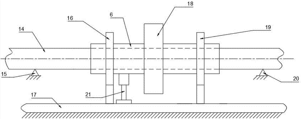
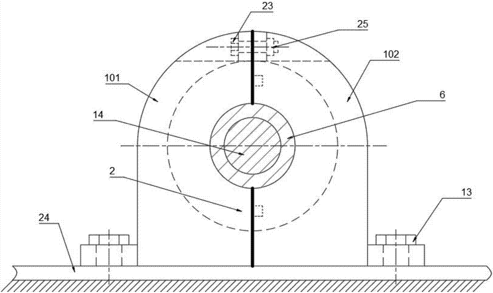
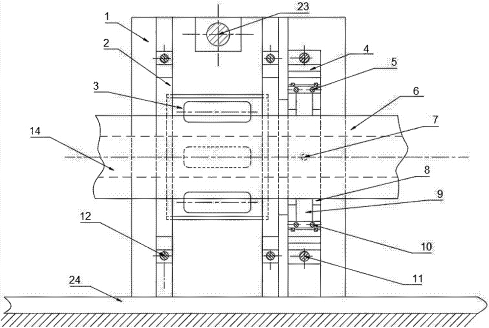
[0030] Such as figure 2 , image 3 As shown, the present invention includes a squirrel-cage elastic support, a squeeze oil film damper 4 , a split rolling bearing 8 , a bearing support 1 and a tenon-connected end face oil retaining ring 5 . The squirrel-cage elastic support, squeeze oil film damper and bearing support 1 are all split structures, and the split plane is a vertical plane passing through the center line of the outer shaft 6 .

[0031] The bearing support 1 is composed of a left half part 101 and a right half part 102. There are through holes above the left half part 101 and the right half part 102, and they are connected as a whole by bolts 23 and nuts 25. Such as Figure 4 , 5 As shown, the squirrel-cage elastic support includes a cylindrical elastic element 3; the cylindrical elastic element 3 is composed of two spring pieces with a semicircular cro...


PUM


Abstract

The invention discloses a split support structure for a turboshaft engine dual-rotor experimental bench comprising a squirrel-cage elastic support, a squeeze film damper, a side-by-side antifriction bearing, a bearing support and tenoned end face oil baffle rings. The squirrel-cage elastic support, the squeeze film damper and the bearing support are all split structures, and the split surfaces arevertical planes passing through the centerline of a shaft. The squeeze film damper and the squirrel-cage elastic support are installed on the bearing support. The side-by-side antifriction bearing isinstalled in the squeeze film damper and a shaft is supported on the side-by-side antifriction bearing. Two parallel oil baffle ring grooves are arranged on the outer ring of the side-by-side antifriction bearing. The tenoned end face oil baffle rings are arranged in the two oil baffle ring grooves. The split support structure is simple, the squirrel-cage elastic support, the squeeze film damper,the bearing and the bearing support can be split, and the bearing support can be replaced easily without disassembling the rotors of the turboshaft engine dual-rotor experimental bench.

Description

technical field [0001] The invention belongs to the technical field of rotor support equipment, and in particular relates to a splittable support structure of a turboshaft engine similar test bench. Background technique [0002] Turboshaft engines are mostly designed with elastic damping support structures, which include squirrel cage elastic supports, squeeze oil film dampers, etc. The rotor system adopts elastic support, the deformation of the support and the internal resistance of the material can play a certain role in damping the vibration of the rotor system, and its more important role is to adjust the critical speed of the rotor system. As modern turboshaft engines meet the high power-to-weight ratio requirements, the rotor becomes more and more flexible, so the support structure plays a very important role in the structural design and vibration analysis of the aeroengine rotor system. [0003] In order to understand the dynamic characteristics of the turboshaft eng...

Claims


Application Information

Patent Timeline
Patent Type & Authority Applications(China)
IPC IPC(8): G01M15/02F16M5/00F16M7/00F16C35/06F16C39/02
CPCF16C35/06F16C39/02F16M5/00F16M7/00G01M15/02
Inventor 宾光富廖子豪郭帅平韩清凯黄源王钢李学军
Owner HUNAN UNIV OF SCI & TECH
Why Eureka
Try Eureka