Steel plate cutting equipment

A technology for cutting equipment and steel plates, applied in welding equipment, metal processing equipment, gas flame welding equipment, etc., can solve the problems of low degree of automation, complicated operation, laborious and other problems, and achieve the effect of saving time, effort and simple operation

Inactive Publication Date: 2018-05-11
李月彩
View PDF0 Cites 4 Cited by
  • Summary
  • Abstract
  • Description
  • Claims
  • Application Information

AI Technical Summary

Problems solved by technology

[0004] The purpose of the invention is to provide a steel plate cutting equipment to solve the problems of complex operation, time-consuming, laborious,

Method used


Image

  • Steel plate cutting equipment
  • Steel plate cutting equipment
  • Steel plate cutting equipment

Examples


Embodiment Construction

[0023] The technical solutions in the embodiments of the present invention will be clearly and completely described below in conjunction with the accompanying drawings in the embodiments of the present invention. Obviously, the described embodiments are only a part of the embodiments of the present invention, rather than all the embodiments. Based on the embodiments of the present invention, all other embodiments obtained by those of ordinary skill in the art without creative work shall fall within the protection scope of the present invention.

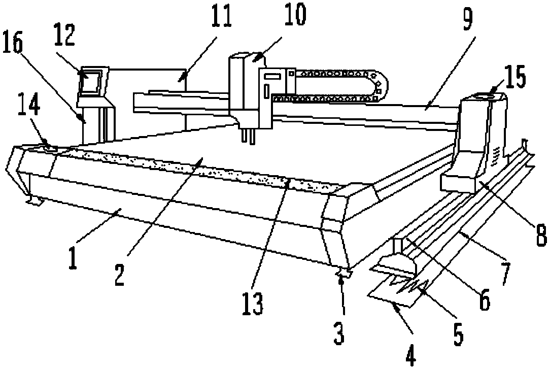
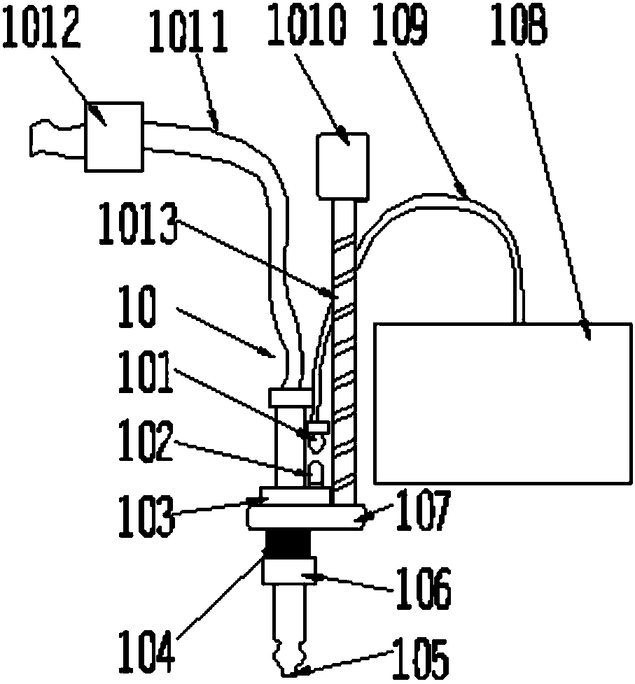
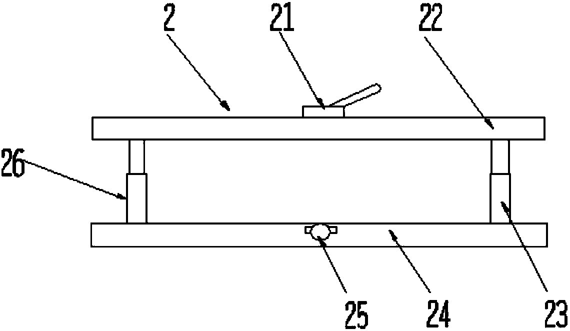
[0024] See Figure 1-5 , The invention provides a technical solution for steel plate cutting equipment: including steel plate cutting equipment body 1, operation panel 2, support frame 3, bottom plate 4, first spring 5, first rail 6, support seat 7, first slider 8, and Two tracks 9, cutting knife device 10, second slider 11, control panel 12, measuring device 13, sensing device 14, alarm device 15, host 16, lock 21, first clamping block ...


PUM


Abstract

The invention discloses steel plate cutting equipment. The steel plate cutting equipment comprises a steel plate cutting equipment body, an operation panel, a supporting frame, a base plate, a first spring, a first rail, a supporting base, a first sliding block, a second rail, a cutter device, a second sliding block, a control panel, a measuring device, a sensing device, an alarming device, a mainmachine, a lock catch, a first clamping block, a first electric push rod, a second clamping block, a solenoid valve, a second electric push rod, a sliding wheel groove, a wheel shaft, a microswitch,a contactor, an upper clamping disc, a second spring, a tool bit, a lower clamping disc, a cutting torch clamp, an automatic height adjusting device, a signal line, a direct-current motor, a cable, aHall sensor and a lead screw, and the lower end of the steel plate cutting equipment body is connected with the supporting frame; and the sensing device is arranged on the upper surface of the steel plate cutting equipment body. The steel plate cutting equipment has the beneficial effects that high efficiency is achieved, the intelligent degree is relatively high, safety is achieved, operation isrelatively convenient, the application scope is wide, and the defective percentage is reduced.

Description

Technical field [0001] The invention relates to the technical field of cutting equipment, in particular to a steel plate cutting equipment. Background technique [0002] A steel plate cutting equipment is to use natural gas flame (oxygen-natural gas) to preheat the cut metal to a burning point that can burn violently, and then release a high-pressure oxygen stream to further oxidize the metal and blow off the slag produced by combustion The process of forming an incision. [0003] However, the current steel plate cutting equipment has the problems of complicated operation, time-consuming, laborious, small scope of application, high defective rate, low degree of automation, unsafe, and poor quality. Summary of the invention [0004] The purpose of the invention is to provide a steel plate cutting equipment to solve the problems of complicated operation, relatively time-consuming, laborious, small application range, low defective rate, low automation, unsafe, and poor quality propose...

Claims


Application Information

Patent Timeline
IPC IPC(8): B23K7/00B23K7/10
CPCB23K7/003B23K7/10B23K7/102
Inventor 李月彩
Owner 李月彩
Why Eureka
Try Eureka