Nuclear magnetic resonance gyroscope photomagnetic modulation detection system and nuclear magnetic resonance gyroscope photomagnetic modulation detection method

A technology of nuclear magnetic resonance gyro and detection system, which is applied to steering induction equipment and other directions, can solve the problems of gyro zero bias stability, restrict gyro accuracy, light intensity, optical path stability, low frequency noise, etc., and meet the accuracy requirements. , the effect of suppressing low-frequency noise and improving carrier capability

Active Publication Date: 2018-05-11
BEIJING AUTOMATION CONTROL EQUIP INST
View PDF5 Cites 4 Cited by
  • Summary
  • Abstract
  • Description
  • Claims
  • Application Information

AI Technical Summary

Problems solved by technology

[0003] At present, the technical solution adopted in the nuclear magnetic resonance gyroscope is still the traditional way of detecting the gyro output by detecting the laser light intensity information, but this detection method is less affected by the laser light intensity, the stability of the optical path, and the low-frequency noise of the detector. Large, it is impossible to effectively isolate these low-frequency interference signals, which reduces the accuracy and stability of the gyro detection system, has a great impact on the stability of the gyro's zero bias, and restricts the further improvement of the gyro's accuracy; and makes the nuclear magnetic resonance gyro high-precision, Theoretical advantages such as insensitivity to acceleration cannot be fully reflected in practical applications
Strict requirements are put forward for the application environment of gyroscopes, which restricts the application range of nuclear magnetic resonance gyroscopes

Method used


Image

  • Nuclear magnetic resonance gyroscope photomagnetic modulation detection system and nuclear magnetic resonance gyroscope photomagnetic modulation detection method

Examples


Embodiment Construction

[0019] The present invention will be further described below by means of the accompanying drawings and specific embodiments.

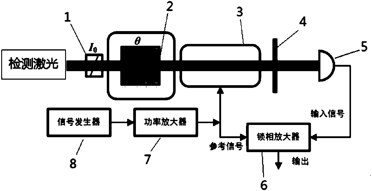
[0020] Such as figure 1 The shown NMR gyro optomagnetic modulation detection system includes a polarizer 1, a magnetic resonance gas chamber 2, a Faraday coil 3, a polarizer 4 and a photodetector 5, and also includes a signal processing system. The centers of the polarizer 1, the magnetic resonance gas chamber 2, the Faraday coil 3, the analyzer 4 and the photodetector 5 are successively located on the optical path of the detection laser, and the axial direction of the Faraday coil 3 coincides with the direction of the optical path of the detection laser. The output end of the device 5 is connected to the input end of the signal processing system, and the Faraday coil 3 receives the driving signal output by the above signal processing system.

[0021] In this embodiment, the signal processing system includes a lock-in amplifier 6 , a power amplifier 7...


PUM


Abstract

The invention belongs to a nuclear magnetic resonance gyroscope detection method, and specifically discloses a nuclear magnetic resonance gyroscope photomagnetic modulation detection system and a nuclear magnetic resonance gyroscope photomagnetic modulation detection method. The nuclear magnetic resonance gyroscope photomagnetic modulation detection system comprises a polarizer, a magnetic resonance gas chamber, a Faraday coil, an analyzer and a photoelectric detector, wherein the centers of the polarizer, the magnetic resonance gas chamber, the Faraday coil, the analyzer and the photoelectricdetector are sequentially positioned on the optical path of detection laser, the axis direction of the Faraday coil coincides with the optical path direction of the detection laser, the output end ofthe photoelectric detector is connected to a signal processing system, and the signal processing system drives the Faraday coil. According to the present invention, the signal output frequency of a signal generator is regulated to be equal to the design frequency of the Faraday coil, the magnetic resonance gas chamber is heated, the modulated laser signal is confirmed when the frequency of the output signal is the same as the frequency of the received drive signal of the Faraday coil, a lock-in amplifier is regulated so as to lock at the frequency of more than the Faraday coil modulation frequency, and then wave filtering treatment is performed; and with the method, the carrier ability of the detection laser and the integrity of the signal after the post-demodulation can be improved, andthe low-frequency noise of the gyroscope detection signal can be inhibited.

Description

technical field [0001] The invention belongs to a nuclear magnetic resonance gyroscope detection method, in particular to a detection system and method capable of isolating low-frequency noise interference inside the gyroscope. Background technique [0002] The nuclear magnetic resonance gyroscope is currently the smallest gyroscope that can achieve navigation-level precision. Its high precision, insensitivity to acceleration, stable scale factor, small size and low power consumption are regarded as the development direction of the next generation of navigation-level precision gyroscopes. . The purpose of the nuclear magnetic resonance gyro is to obtain the rotational angular rate of the carrier by detecting the oscillation frequency of the atomic source and subtracting the oscillation frequency of the atomic source itself. Therefore, the high-precision nuclear magnetic resonance gyroscope puts forward higher requirements for its detection system. [0003] At present, the ...

Claims


Application Information

Patent Timeline
Patent Type & Authority Applications(China)
IPC IPC(8): G01C19/60
CPCG01C19/60
Inventor 秦杰孙晓光万双爱刘建丰田晓倩
Owner BEIJING AUTOMATION CONTROL EQUIP INST
Why Eureka
Try Eureka