
Partial discharge denoising method

A partial discharge and partial technology, applied in the field of partial discharge denoising, can solve the problems of endpoint effect and frequency confusion, meet the processing requirements of real-time and continuity, have small edge effect, and improve the effect of signal-to-noise ratio

Inactive Publication Date: 2018-05-11
CHINA INST OF WATER RESOURCES & HYDROPOWER RES
View PDF6 Cites 3 Cited by
  • Summary
  • Abstract
  • Description
  • Claims
  • Application Information

AI Technical Summary

Problems solved by technology

The EMD method can adaptively separate the random noise and the partial discharge signal, so as to suppress the interference, but there are problems such as over-envelope, under-envelope, endpoint effect and frequency confusion.

Method used


Image

  • Partial discharge denoising method
  • Partial discharge denoising method
  • Partial discharge denoising method

Examples


Embodiment 1

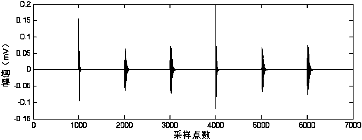
[0055] Use the partial discharge simulation signal for denoising analysis: the partial discharge signal is generally an oscillation attenuation signal, and the simulation signal can be described by a single exponential attenuation oscillation model and a double exponential attenuation oscillation model.

[0056] Single Exponential Decay Oscillation:

[0057] the s 1 (t) = Ae -t / τ sin2πf c t (4)

[0058] Double Exponential Decay Oscillation:

[0059]

[0060] In the formula: A is the signal amplitude, τ, τ 1 , τ 2 is the attenuation coefficient, f c is the oscillation frequency.

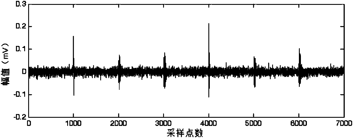
[0061] As shown in Figure 2(a) and Figure 2(b), they are the simulated partial discharge signal and the noised partial discharge signal respectively. During the simulation, the values ​​of each parameter in the single exponential damping oscillation model are: τ=1μs, f c =1MHz, A is 0.2mV, 0.25mV respectively; each parameter value in the double exponential damping oscillation model is: τ ...

Embodiment 2

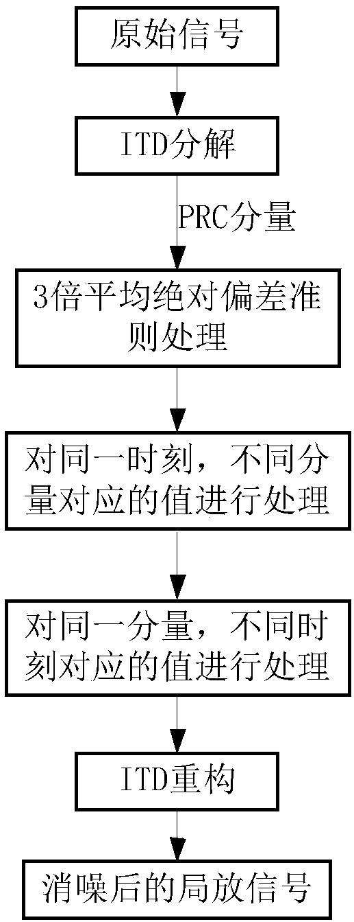
[0075] Such as Figure 5 , Figure 6 As shown, a certain DC partial discharge test data is selected to test the noise canceling performance of the present invention. The sampling frequency of the test is 1GHz, and the number of sampling points is 1×10 5 from Figure 5 It can be seen that the partial discharge signal contains a lot of background noise. ITD decomposition is performed on the signal to obtain 8 PRC components and a trend margin. Calculate the average absolute deviation value of each PRC component, and extract the partial discharge signals of 8 PRC components according to the set threshold; then process the values ​​corresponding to different components at the same time; The value is processed; it is reconstructed to obtain the denoised waveform as Figure 6 shown. From Figure 6 It can be seen from the figure that the method of the present invention can well remove a large amount of background noise contained in the partial discharge signal.


PUM


Abstract

The present invention relates to a partial discharge denoising method. The method comprises the following steps of: 1) employing an ITD decomposition method to perform adaptive decomposition of original partial discharge signals including noise, and obtaining a plurality of proper rotation components (PRC) including noise; 2) determining the denoising threshold of each PRC, performing processing of each PRC according to the obtained denoising thresholds, and obtaining the preliminary denoising result of each PRC; 3) performing processing of each PRC after the preliminary denoising according tothe energy of each PRC, removing burrs at singular points after preliminary denoising, and obtaining each processed PRC; and 4) performing ITD reconstruction of each PRC obtained in the step 3), andobtaining partial discharge signals after denoising. The method has adaptivity, a good denoising performance and a fast calculation speed, can greatly remove a lot of background noise included in thepartial discharge signals, and can be widely applied in the online monitoring field of insulation of electric devices.

Description

technical field [0001] The invention relates to the technical field of on-line monitoring, in particular to a partial discharge noise reduction method. Background technique [0002] Partial discharge detection is an important means to monitor the insulation of power equipment. Due to the weak nature of the partial discharge signal, when there are a large number of interference signals on site, the partial discharge signal is easily overwhelmed by noise, and it is difficult to accurately determine the time and amplitude of the partial discharge pulse. Therefore, it is of great significance to extract the partial discharge signal from the noise accurately and quickly to eliminate the fault (abnormality) of the power equipment in time. [0003] Currently widely used PD denoising algorithms include wavelet and EMD methods. The wavelet analysis method has certain advantages in removing narrow-band periodic interference, but there are some problems in this method, such as diffic...

Claims


Application Information

Patent Timeline
Patent Type & Authority Applications(China)
IPC IPC(8): G01R31/12
Inventor 安学利潘罗平赵明浩
Owner CHINA INST OF WATER RESOURCES & HYDROPOWER RES
Learn More