
Suspended microstrip filtering device and microstrip filtering device

A microstrip filtering and filter technology, applied in the field of communication systems, can solve the problems of expensive manufacturing, processing and assembly

Active Publication Date: 2018-05-11
COMMSCOPE ITAL SRL
View PDF7 Cites 1 Cited by
  • Summary
  • Abstract
  • Description
  • Claims
  • Application Information

AI Technical Summary

Problems solved by technology

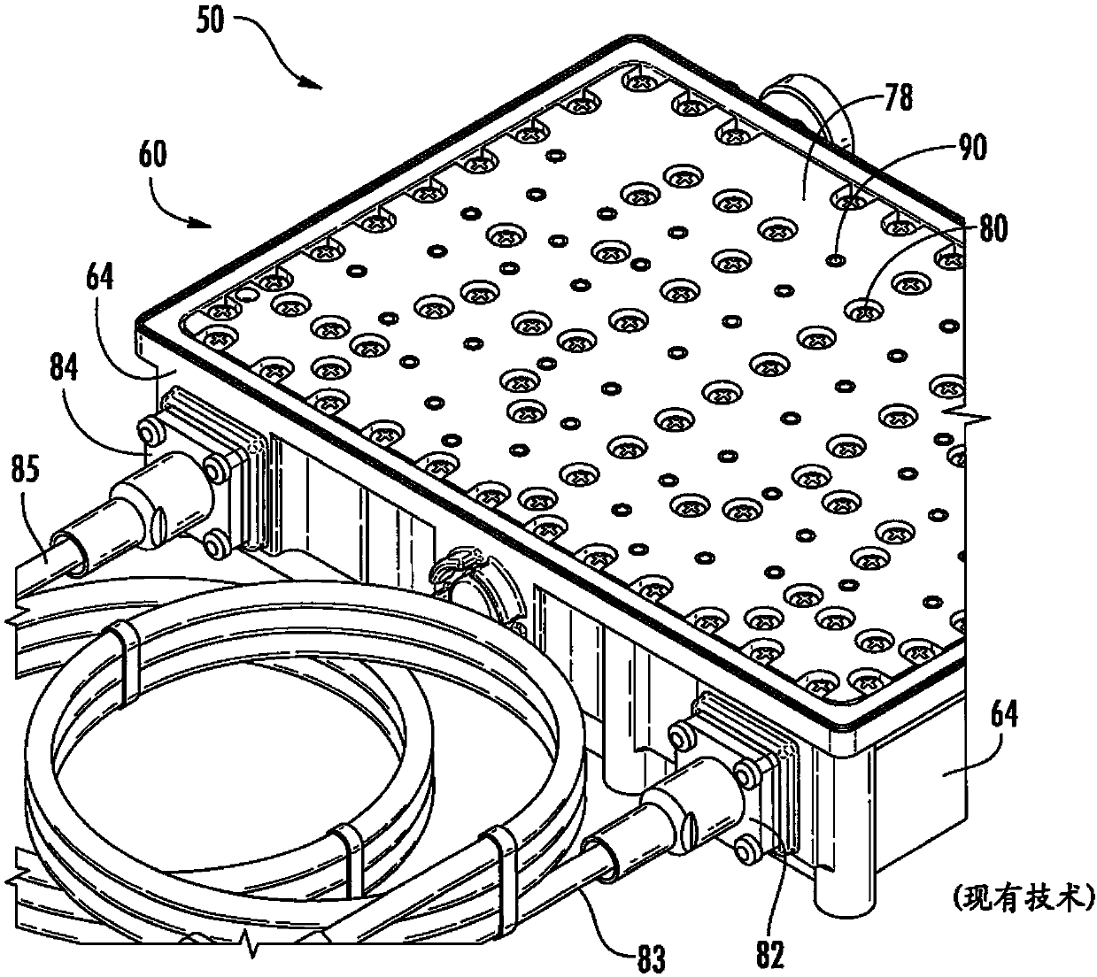
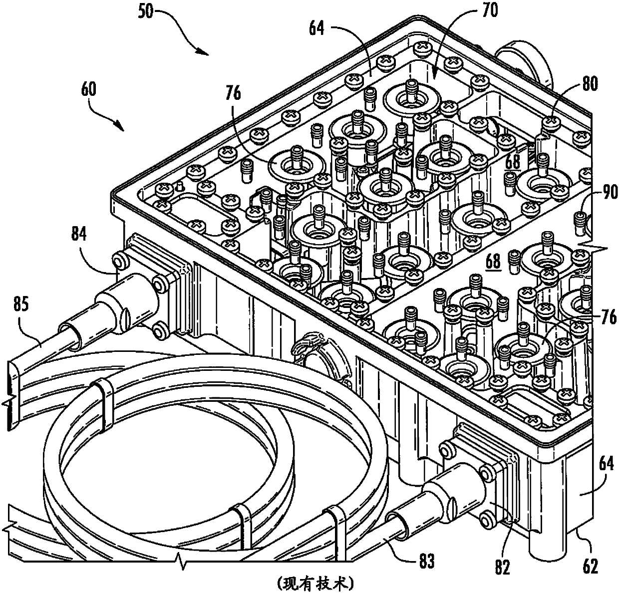
The diplexer 50 also has a large number of parts, making manufacturing tooling and assembly more expensive

Method used


Image

  • Suspended microstrip filtering device and microstrip filtering device
  • Suspended microstrip filtering device and microstrip filtering device
  • Suspended microstrip filtering device and microstrip filtering device

Examples


Embodiment Construction

[0036] As the number of cellular subscribers and the amount of data transmitted and received by those subscribers continues to increase rapidly, wireless carriers are constantly looking for ways to increase throughput. Wireless carriers have purchased additional wireless spectrum, but even deploying additional frequency bands and service types is not enough to keep up with the increased demand. Therefore, wireless operators are also strongly taking steps to increase the throughput of existing wireless resources. One way to do this is to deploy multiple remote cell sites that are smaller than traditional base stations, using frequency division multiplexers to divide the entire available bandwidth into a series of non-overlapping frequency bands. This approach can significantly increase the achievable throughput, but it is important that the remote site is not more expensive than a traditional base station, while still providing high performance.

[0037] In the cellular commun...


PUM


Abstract

The invention provides a suspended microstrip filtering device and a microstrip filtering device. The suspended microstrip filtering device comprises a PCB which comprises a substrate including at least one resonator, a grounding board, and an insulated separator which is inserted between the PCB and the grounding board and includes multiple inflation openings.

Description

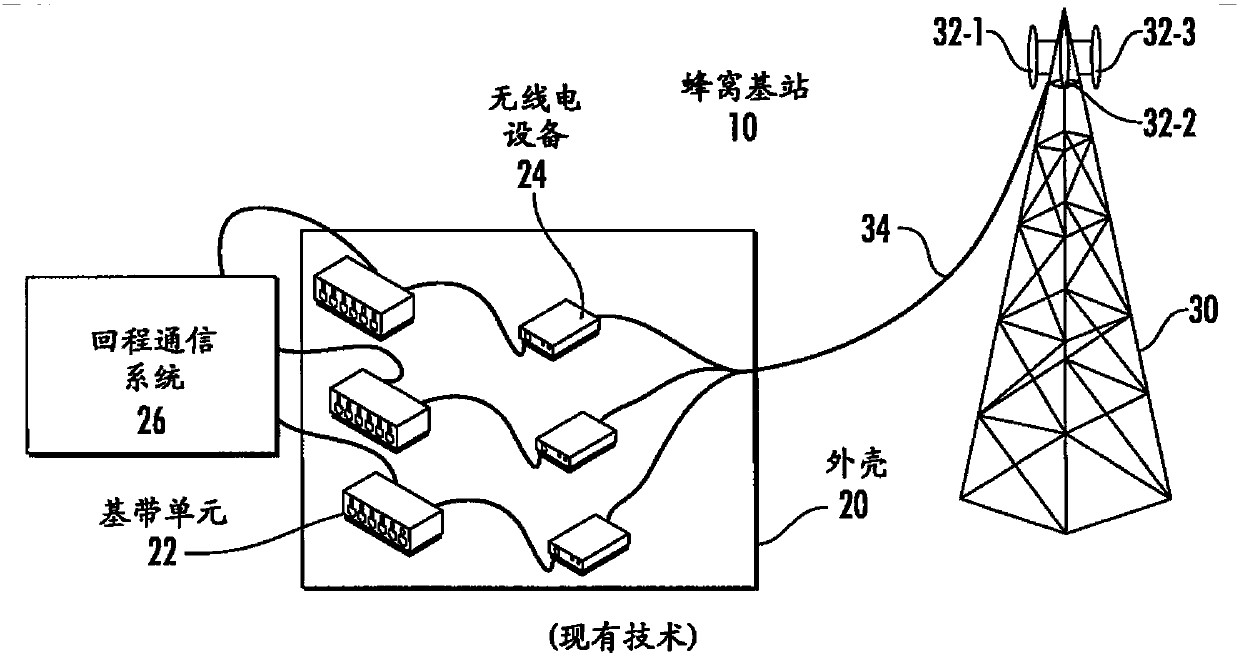
technical field [0001] The present invention relates generally to communication systems, and more particularly to filtering arrangements suitable for use in cellular communication systems. Background technique [0002] Cellular base stations are well known in the art and typically include baseband equipment, radio equipment and antennas, among other components. figure 1 is a highly simplified schematic diagram showing a conventional cellular base station 10 . Such as figure 1 As shown in , the cellular base station 10 includes an antenna tower 30 and an equipment housing 20 located at the bottom of the antenna tower 30 . A plurality of baseband units 22 and radios 24 are located within the device housing 20 . Each baseband unit 22 is connected to a respective one of the radios 24 and also communicates with a backhaul communication system 26 . Three antennas 32 (labeled antennas 32 - 1 , 32 - 2 , 32 - 3 ) are located on top of the antenna tower 30 . Each antenna 32 may p...

Claims


Application Information

Patent Timeline
IPC IPC(8): H01P1/203
CPCH01P1/20381H01P1/20336H01P1/2135H01P5/04H01P3/087H05K1/145
Inventor 王欢汪玉华G·瑞斯纳缇
Owner COMMSCOPE ITAL SRL
Learn More