Reflectionless bridge filter

A filter and bridge technology, applied in the field of non-reflection bridge filters, can solve the problems of single response and complicated design of non-reflection filters, and achieve the effects of simple structure, cascade improvement, and rapid design and production.

Inactive Publication Date: 2018-05-11
NANJING UNIV OF POSTS & TELECOMM
View PDF6 Cites 8 Cited by
  • Summary
  • Abstract
  • Description
  • Claims
  • Application Information

AI Technical Summary

Problems solved by technology

[0005] The technical problem to be solved by the present invention is to overcome the deficiencies of the prior art, provide a non-reflection bridge filter, and realize a non-reflection filter with a customizable response, so as to solve the problem of single response and cumbersome design of the existing non-reflection filter And other issues

Method used


Image

  • Reflectionless bridge filter
  • Reflectionless bridge filter
  • Reflectionless bridge filter

Examples


Embodiment 1

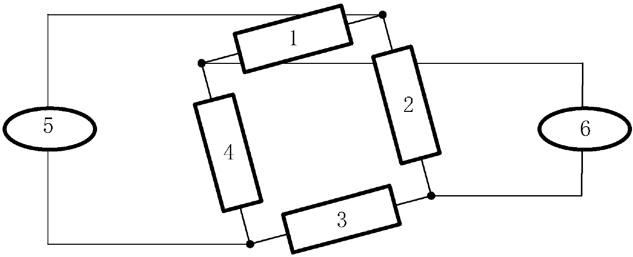
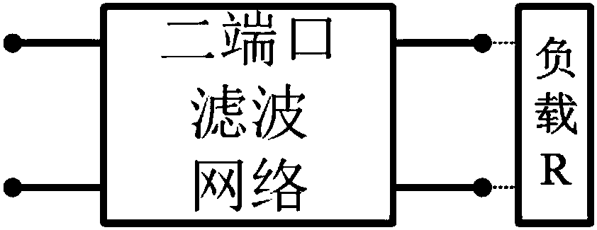
[0049] In this example, if figure 2 As shown, each one-port circuit sub-network is implemented by using a two-port reflective filter network 7 connected to a load, which is not limited in the present invention.

[0050] In this embodiment, a port reference impedance of 50Ohm is used, namely R 0 =50Ω, the present invention does not limit it.

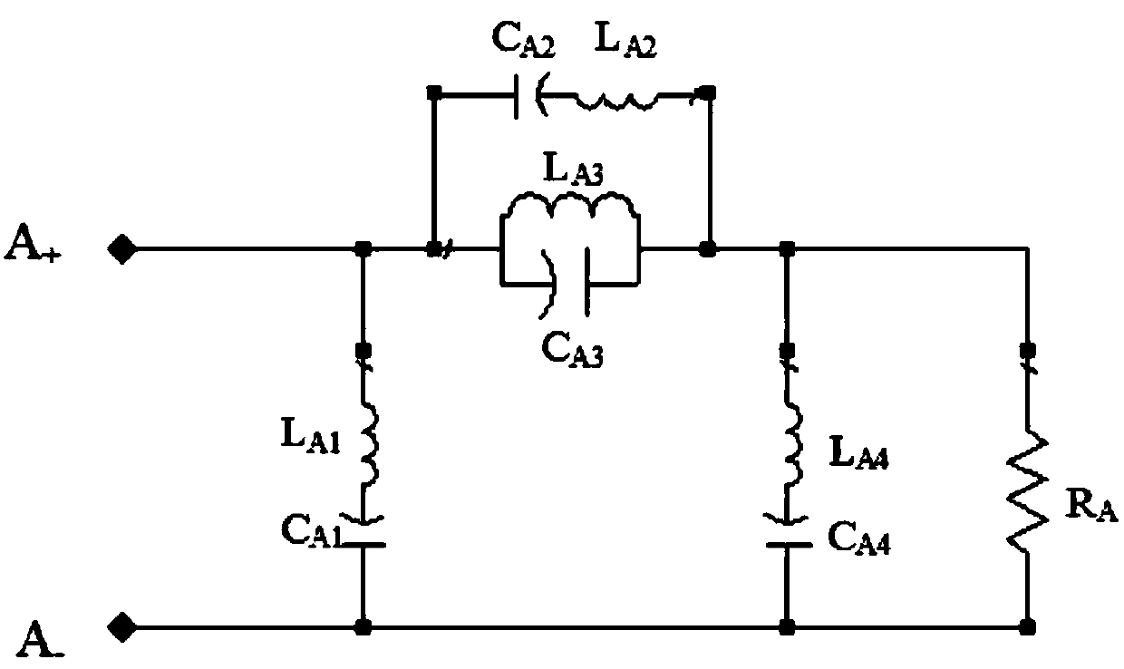
[0051] In this embodiment, an elliptic function bandpass filter design based on lumped elements is adopted, which is not limited in the present invention.

[0052] In this embodiment, the same single-port circuit sub-network circuit design is adopted, that is, the first single-port circuit sub-network 1 or the third single-port circuit sub-network 3 are completely the same, and the second single-port circuit sub-network 2 or the fourth The single-port circuit sub-network 4 is completely the same, which is not limited in the present invention.

[0053] In this embodiment, a design in which adjacent single-port circuit sub-networks are ...

Embodiment 2

[0061] In the present embodiment, as shown in Fig. 5 (e), utilize ideal transmission line structure, the present invention has designed a kind of reflectionless filter, comprise: input port 5 and output port 6, two single-port transmission line sub-networks 12 and 13 ; Its bridge connection mode is the same as implementation example 1, and will not be described in detail here, such as figure 1 . The specific design method of this type of transmission line filter is briefly described below.

[0062] The goal of this implementation example is a reflectionless bandpass filter with a transmission line structure. In order to simplify the design process, this implementation example uses a terminal load with a normalized impedance of 1Ohm and an input and output reference port; the adjacent subnetworks are dual , The overall network design in which non-adjacent sub-networks are identical. The present invention is not limited thereto.

[0063] As shown in Fig. 5(a), the transmissio...


PUM


Abstract

The invention discloses a reflectionless bridge filter. The reflectionless bridge filter comprises four independent single-port circuit subnetworks, an input port, and an output port, wherein each single-port circuit subnetwork is provided with two endpoints, the four single-port circuit subnetworks are sequentially connected through the respective endpoints to form a ring, one endpoint of the input port is connected to a common endpoint of a first single-port circuit subnetwork and a second single-port circuit subnetwork, the other endpoint is connected to a common endpoint of a third single-port circuit subnetwork and a fourth single-port circuit subnetwork, one endpoint of the output port is connected with a common endpoint of the second single-port circuit subnetwork and the third single-port circuit subnetwork, and the other endpoint of the output port is connected to a common endpoint of the first single-port circuit subnetwork and the fourth single-port circuit subnetwork, so that a reflectionless bridge filter circuit is formed. The reflectionless bridge filter provided by the invention has the advantages that various kinds of filter responses can be flexibly achieved, andreflectionless high-performance filter responses can be achieved; the structure is applicable for filter designs with various frequency bands; and a simple structure, excellent performance and the like are achieved.

Description

technical field [0001] The invention relates to a reflectionless bridge filter, which belongs to the technical field of electronic circuits. Background technique [0002] A filter is an electronic device that is widely used in various electronic systems. Such devices generally have two ports that allow electrical signals in the passband to pass through without loss or with low loss, while prohibiting electrical signals in the stopband from being transmitted between the two ports. [0003] Most filters are reflective. In this type of filter, according to the law of energy conservation, if the input electrical signal at the input terminal is within the passband, it will be transmitted to the output terminal; if it is within the stop band, it will be totally reflected to the input terminal, and there will be no signal output at the output terminal at this time. If the power of the reflected signal is large, it will have an uncertain impact on the subsequent circuits after ret...

Claims


Application Information

Patent Timeline
Patent Type & Authority Applications(China)
IPC IPC(8): H03H7/01
CPCH03H7/0153
Inventor 黄晓东金秀华
Owner NANJING UNIV OF POSTS & TELECOMM
Why Eureka
Try Eureka