Grinding machine tool for drum type brake pad

A technology of brake pads and grinding mechanism, which is applied to the parts of grinding machine tools, grinding machines, grinding drive devices, etc. The effect of labor intensity, avoidance of re-cleaning, and concentrated effect

Active Publication Date: 2018-05-15
宁波江北珂达汽车技术有限公司
View PDF5 Cites 2 Cited by
  • Summary
  • Abstract
  • Description
  • Claims
  • Application Information

AI Technical Summary

Problems solved by technology

[0004] The present invention intends to provide a grinding machine tool for drum brake pads to solve the technical problem that waste debris splashes during drum brake pad grinding and affects the normal operation of other mechanisms

Method used


Image

  • Grinding machine tool for drum type brake pad
  • Grinding machine tool for drum type brake pad

Examples


Embodiment 1

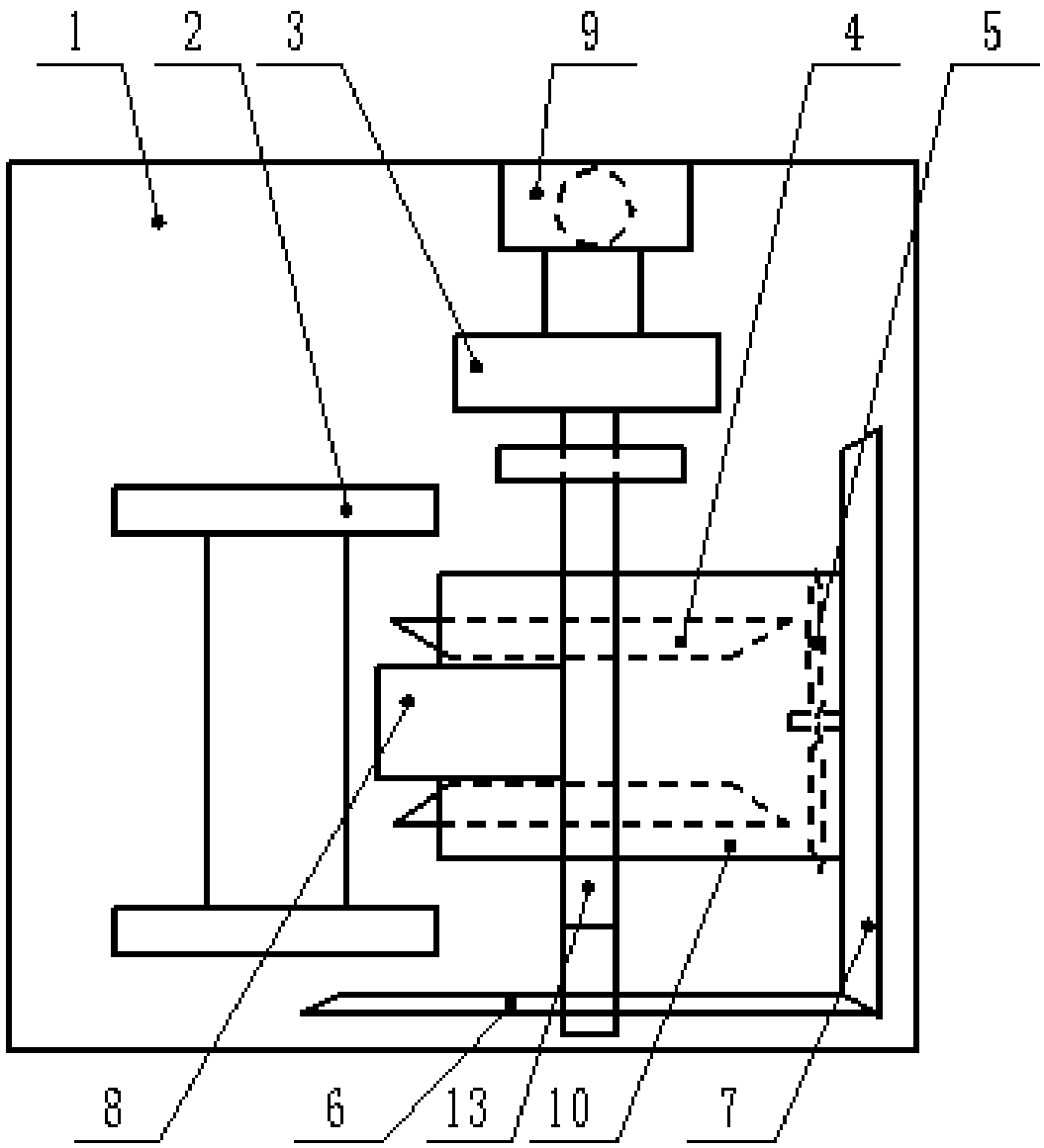
[0023] Drum brake pad grinding machines such as figure 1 As shown, it includes a bed body 1 of a machine tool, on which a base 2 for fixing drum brake pads is installed, and also includes a grinding mechanism cooperating with the base 2 and a horizontal telescopic cylinder 9 for controlling the movement of the grinding mechanism. The horizontal telescopic cylinder 9 is welded on the bed body 1 by a support.

[0024] The grinding mechanism includes a grinding unit and a negative pressure unit for processing waste from the grinding unit. The grinding unit includes a motor 3, which is welded to the output shaft of the horizontally telescopic cylinder 9, and the output shaft of the motor 3 is coaxially welded with a grinding wheel unit 4, and each grinding wheel unit 4 has a cover 10 outside, and the left side of the cover 10 has an opening , The grinder unit 4 is composed of two grinders with a gap between the two grinders. In this embodiment, the grinder is provided with a cha...

Embodiment 2

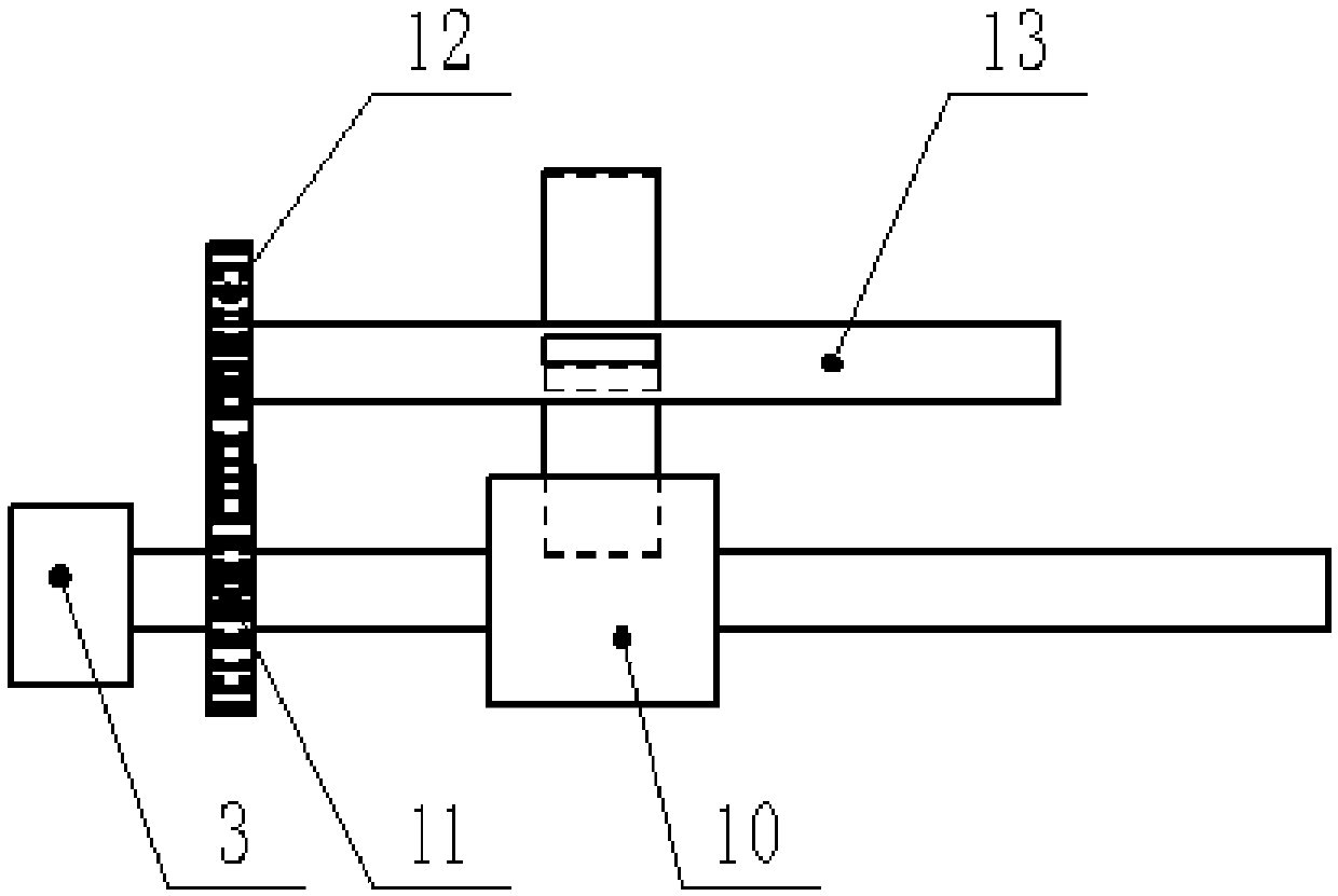
[0028] The difference between this drum type brake pad grinding machine tool and Embodiment 1 is: (1) In this embodiment, grinding mechanisms are symmetrically provided on both sides of the base 2 . (2) The side where the fan 5 is away from the grinder and the contact side of the drum brake pad is connected with a guide pipe. (3) if figure 2 As shown, the number of blocking pieces 8 is four, and they are uniformly welded on the rotating shaft 13 in the circumferential direction. Compared with the single-side grinding of the grinding mechanism, the two grinding mechanisms in this scheme can simultaneously grind the drum brake pads, making the grinding efficiency higher. After the guide tube makes the negative pressure generated by the fan 5 act on the waste, the guide tube concentrates the waste to avoid re-cleaning of the waste in the later stage, which reduces labor intensity and improves efficiency. The circumferentially uniform baffles 8 can be rotated sequentially with ...


PUM


Abstract

The invention belongs to the technical field of grinding machine tools, and particularly discloses a grinding machine tool for a drum type brake pad. The grinding machine tool comprises a machine toolbody and a base, and further comprises a grinding mechanism and a horizontal telescopic air cylinder, wherein the grinding mechanism is matched with the base, and the horizontal telescopic air cylinder controls the grinding mechanism to horizontally move; the grinding mechanism comprises a grinding unit and a negative pressure unit, wherein the negative pressure unit processes waste scraps of thegrinding unit; the grinding unit comprises a motor; an output shaft of the motor is coaxially connected with a plurality of grinding wheel units; a cover is arranged outside each grinding wheel unit;each grinding wheel unit is composed of two grinding wheel machines, and a gap is formed between every two grinding wheel machines; and the negative pressure unit comprises a fan, a bevel gear set, ablocking sheet and a connecting mechanism of the blocking sheet, wherein the fan generates the negative pressure, the bevel gear set can enable the fan to act accurately, and the blocking sheet blocks the waste scraps. According to the technical scheme of the grinding machine tool, the technical problem that normal operation of other mechanisms is influenced due to the fact that the waste scrapsspatter in the grinding process of the drum type brake pad can be solved, and therefore the grinding machine tool can be widely used for grinding the drum type brake pad.

Description

technical field [0001] The invention relates to the technical field of grinding machine tools, in particular to a drum brake pad grinding machine tool. Background technique [0002] During the processing of automobile drum brake pads, it is necessary to grind the marking holes and observation holes. The traditional processing method is manual processing. This traditional manual processing method affects the processing efficiency. [0003] A grinding machine for automobile drum brake pads is proposed in the prior art, and a grinder is used to grind the automobile drum brake pads, but waste chips will be splashed randomly during grinding by this grinding device. In the prior art, for the sake of precision when grinding drum brake pads, a lead screw is provided on the machine tool, and debris flying randomly affects the movement of the lead screw, resulting in insufficient grinding accuracy. Therefore, if the waste chips during grinding are not treated, the machining accuracy ...

Claims


Application Information

Patent Timeline
Patent Type & Authority Applications(China)
IPC IPC(8): B24B27/00B24B55/06B24B47/12B24B55/04
CPCB24B27/0076B24B47/12B24B55/04B24B55/06
Inventor 王健
Owner 宁波江北珂达汽车技术有限公司
Why Eureka
Try Eureka