Robot joint movement device

A technology of robot joints and motion devices, applied in manipulators, program-controlled manipulators, manufacturing tools, etc., can solve problems such as limited range of joint motion, difficult design and processing, and complex structures

Inactive Publication Date: 2018-05-15
CHANGSHA ZHIWEI ELECTRONICS TECH CO LTD
View PDF2 Cites 1 Cited by
  • Summary
  • Abstract
  • Description
  • Claims
  • Application Information

AI Technical Summary

Problems solved by technology

For example, Chinese patent 2012101913253 discloses a "reducer, mechanical arm and mechanical hand", which adopts the structure of revolving gear and eccentric cam, which has complex structure, difficult design and processing, poor motion accuracy, and limited range of joint motion.

Method used


Image

  • Robot joint movement device
  • Robot joint movement device

Examples


Embodiment Construction

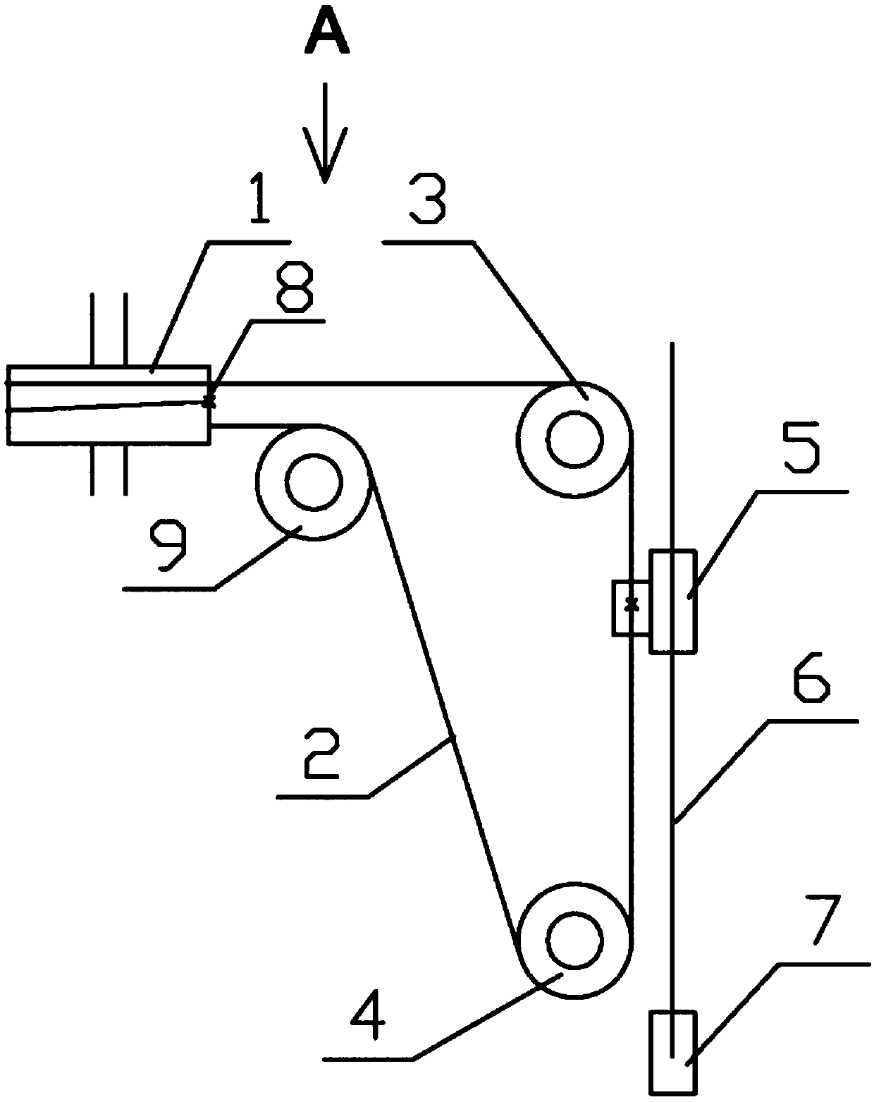
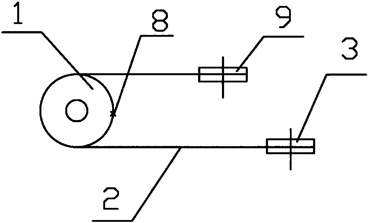
[0010] As shown in the drawings, the robot joint motion device of the present invention includes a balance wheel 1 connected to the joint body, and a flexible rope cover 2 is wound on the balance wheel 1, and the flexible rope cover 2 is also set on a plurality of The transition wheel 3, 4, 9 forms a circular transmission route; the transition wheel 3, 4, 9 and the balance wheel 1 are rotatable wheels, and the balance wheel is not parallel to the axis of the transition wheel, but is vertical or at a certain angle lean state. The flexible rope sheath 2 is tightly wound on the balance wheel 1, and said flexible rope sheath 2 is wound on the balance wheel 1 at least once, and the outer circumference of the balance wheel 1 is fixedly provided with a fixed clip that is clamped on the flexible rope sheath 2 8. Fix the flexible rope cover 2 on the balance wheel 1. A screw nut 5 is fixedly installed on the flexible rope sleeve 2, and the screw nut 5 is fitted on the lead screw 6 thro...


PUM


Abstract

The invention provides a robot joint movement device. The robot joint movement device comprises an oscillating wheel connected to a joint body, wherein a flexible rope sleeve is wound on the oscillating wheel, and meanwhile is further mounted on a plurality of transition wheels in a sleeving manner to form a ring-shaped transmitting path; a nut is fixedly mounted on the flexible rope sleeve, and is cooperatively mounted on a lead screw in a threaded fit manner; one end of the lead screw is in transmission connection with a motor; the flexible rope sleeve is wound on the oscillating wheel at acircle at least; and a fixing clamp which is in clamped connection to the flexible rope sleeve is fixedly arranged on the outer periphery of the oscillating wheel. The robot joint movement device is simple in structure, convenient to machine and manufacture and small in movement gap, is used for driving a robot joint to move, and is high in accuracy and large in oscillating amplitude.

Description

technical field [0001] The invention relates to a robot joint motion device. Background technique [0002] The movement of the robot joints is mostly driven by the motor through the cycloid or gear reducer. During the operation, there is inevitably a movement gap, which will amplify this mechanical error when it is reflected in the action of the robot joint and the mechanical arm, resulting in Movement precision is not high. To this end, it is necessary to design gears with complex structures and precise processing to reduce errors as much as possible. For example, Chinese patent 2012101913253 discloses a "reducer, mechanical arm and mechanical hand", which adopts a structure of a revolving gear and an eccentric cam, which has a complex structure, difficult design and processing, poor motion accuracy, and limited joint motion range. Contents of the invention [0003] The object of the present invention is to provide a robot joint motion device with simple structure, conv...

Claims


Application Information

Patent Timeline
IPC IPC(8): B25J17/00B25J9/10B25J9/12
CPCB25J17/00B25J9/1035B25J9/104B25J9/126
Inventor 不公告发明人
Owner CHANGSHA ZHIWEI ELECTRONICS TECH CO LTD
Why Eureka
Try Eureka