Centrifugal washing equipment and centrifugal washing method

A technology for centrifugal washing and equipment, which is applied in biochemical equipment and methods, biochemical cleaning devices, bioreactors/fermenters for specific purposes, etc., and can solve problems such as low efficiency, large floor space, and high labor intensity.

Active Publication Date: 2018-05-15
广州承葛生物科技有限公司 +1
View PDF8 Cites 1 Cited by
  • Summary
  • Abstract
  • Description
  • Claims
  • Application Information

AI Technical Summary

Problems solved by technology

[0004] Manual operation, low efficiency and high

Method used


Image

  • Centrifugal washing equipment and centrifugal washing method
  • Centrifugal washing equipment and centrifugal washing method
  • Centrifugal washing equipment and centrifugal washing method

Examples


Embodiment 1

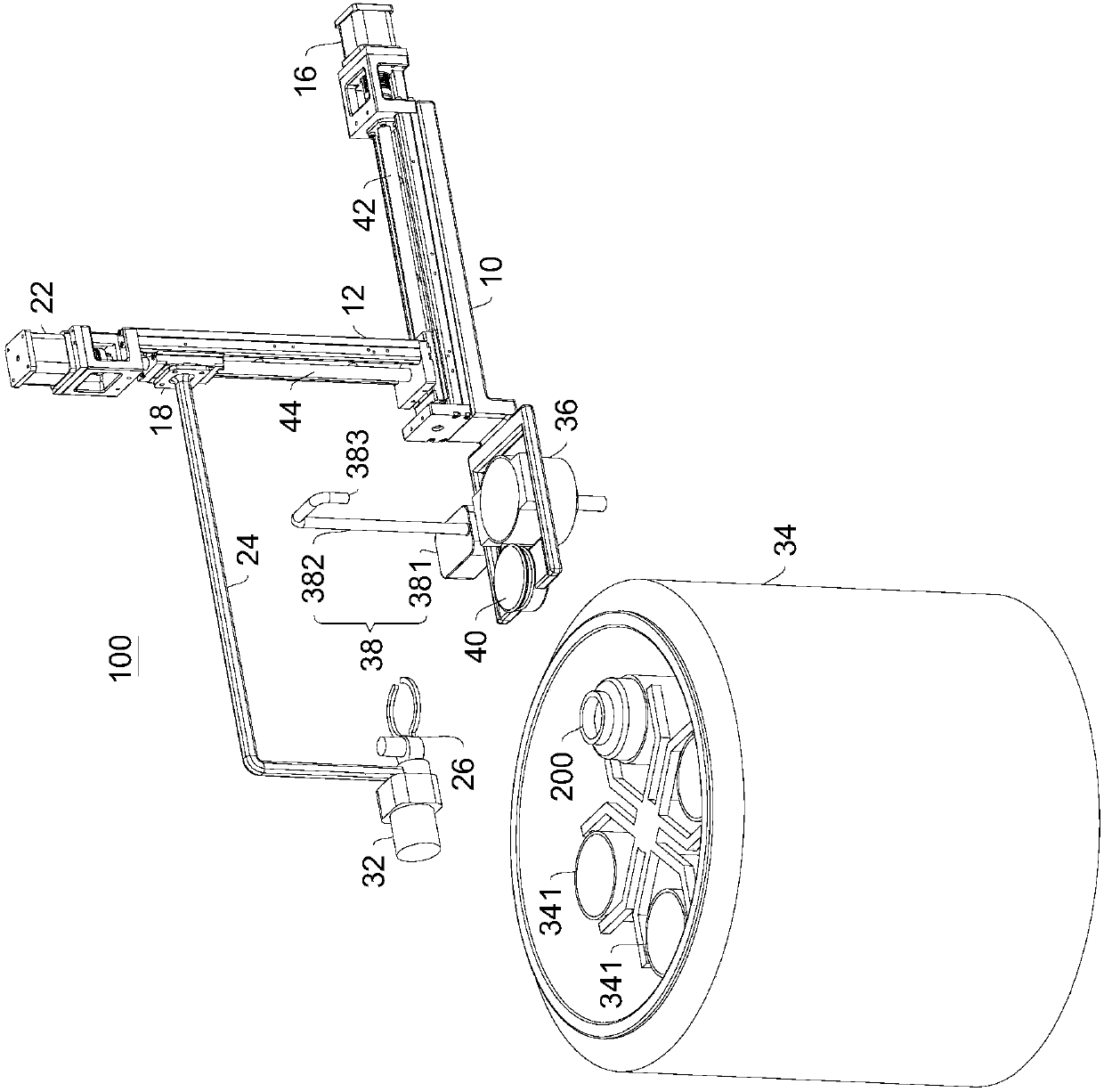
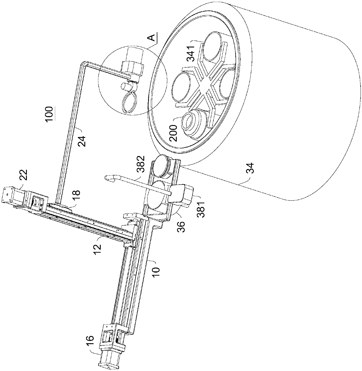
[0057] Please refer to Figure 1-Figure 6 , the present embodiment provides a centrifugal washing device 100, which includes:

[0058] Rack 10;

[0059] The first sliding member 12, the first sliding member 12 is slidably connected to the frame 10 along the first axis 14;

[0060] The first driving member 16, the first driving member 16 is connected with the frame 10 and used to drive the first sliding member 12;

[0061] The second sliding member 18, the second sliding member 18 is slidably connected to the first sliding member 12 along the second axis 20, the first axis 14 is arranged horizontally, and the second axis 20 is arranged vertically;

[0062] The second driving member 22, the second driving member 22 is connected with the first sliding member 12 and used to drive the second sliding member 18;

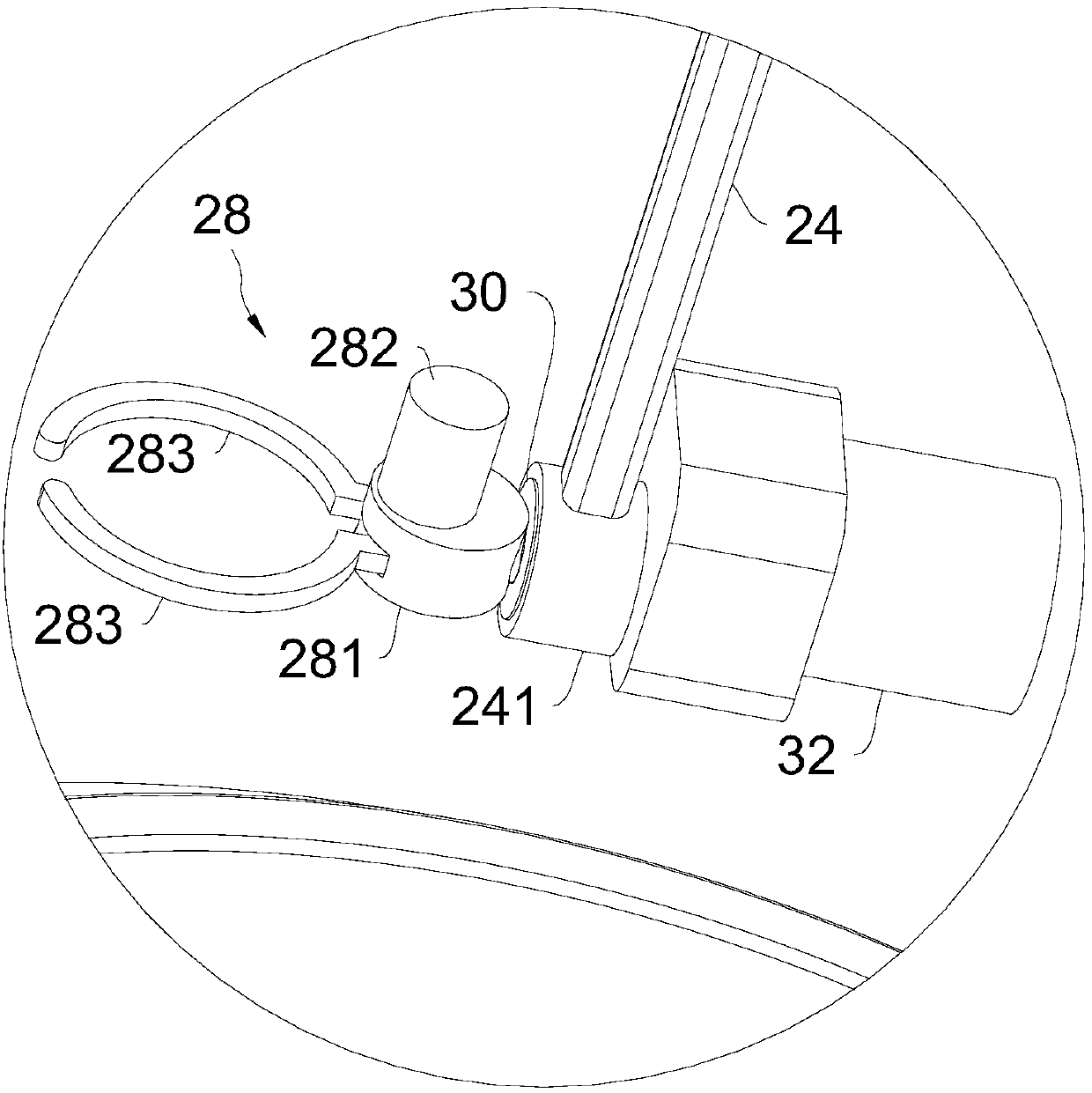
[0063] A connecting piece 24, one end of the connecting piece 24 is connected to the second sliding piece 18, and the other end of the connecting piece 24 is provided wi...

Embodiment approach

[0077] In one embodiment, the structure of the vibrating table 40 includes a motor, a cam mechanism and a vibrating platform. The motor makes the vibrating platform reciprocate quickly through the cam mechanism, thereby producing a vibrating effect. Generally, the base of the vibrating table 40 is fixed on the machine. 10 to improve the integration effect of the entire device.

[0078] In one embodiment, the mechanical clamping hand 26 is a clamper, which can be an electric clamper or a pneumatic clamper, as long as the centrifuge tank 200 can be clamped or loosened.

[0079] Generally, the first axis 14 can be understood as the X axis, and the second axis 20 can be understood as the Z axis. The horizontal and vertical here do not mean absolute horizontal or vertical, and certain deviations are allowed in specific implementation.

[0080] The first driving member 16 , the second driving member 22 and the third driving member 32 can be motors, electric cylinders, air cylinders,...

Embodiment 2

[0116] This embodiment provides a centrifugal washing method, which uses the centrifugal washing equipment 100 mentioned above, and the structure of the centrifugal washing equipment 100 can refer to Example 1.

[0117] The method includes:

[0118] The mechanical gripper 26 is located above the centrifuge 34;

[0119] After the centrifuge 34 completes the centrifugal operation, the centrifuge 34 is opened, and the control device controls the second driving member 22, so that the mechanical clamping hand 26 is stretched into the centrifuge 34, and the centrifuge tank 200 in the centrifuge 34 is clamped, and the The mechanical clamping hand 26 is promoted;

[0120] The control device controls the first driving member 16 to move the mechanical clamping hand 26 to the top of the waste liquid pourer 36, and the control device controls the third driving member 32 to dump the centrifuge tank 200. After the centrifuge tank 200 is dumped, the control device Control the third driving...


PUM


Abstract

The invention provides centrifugal washing equipment and a centrifugal washing method, and belongs to the technical field of microorganism centrifugal washing. The centrifugal washing equipment comprises a rack, a first sliding part, a first driving part, a second sliding part, a second driving part, a connecting part, a mechanical clamping hand, a third driving part, a centrifugal machine, a waste liquid pouring device, an injecting device, a vibration table and a control device, wherein the first sliding part is slidably connected to the rack along a first axis; the first driving part is connected with the rack and is used for driving the first sliding part; the second sliding part is slidably connected to the first sliding part along a second axis; the first axis is horizontally arranged; the second axis is vertically arranged; the second driving part is connected with the first sliding part and is used for driving the second driving part. The centrifugal washing equipment can automatically complete the centrifugal washing process, so that the labor intensity is greatly reduced, the work efficiency is obviously improved, and the centrifugal washing equipment is simple in structure, reasonable in design, relatively low in investment cost, high in practicability and huge in market application potential.

Description

technical field [0001] The invention relates to the technical field of microbial centrifugal washing, in particular to a centrifugal washing device and a centrifugal washing method. Background technique [0002] At present, the centrifugal washing process in the microbial extraction process, that is, repeating the operation process of "centrifugation-discarding the supernatant-adding buffer to wash-adding buffer to disperse and mix the sediment" is manually completed by the experimenter. [0003] The inventor found in the research that there are at least the following shortcomings in the existing related technologies: [0004] Manual operation, low efficiency and high labor intensity; [0005] The floor area is large, and the input cost is high. Contents of the invention [0006] The object of the present invention is to provide a kind of centrifugal washing equipment, improve the deficiencies of the prior art, it can automatically complete the centrifugal washing proces...

Claims


Application Information

Patent Timeline
IPC IPC(8): C12M1/00C12M1/36C12M1/34
CPCC12M41/00C12M41/48C12M47/02
Inventor 刘裕杨晓宁肖传兴何剑全刘丹阳
Owner 广州承葛生物科技有限公司
Why Eureka
Try Eureka