
Sun tracking device and optical fiber sunshine lighting system with sun tracking device

A sun tracking and lighting system technology, applied in the field of solar lighting, can solve the problems of photosensitive sensor consistency check, increase equipment operating cost, limit product promotion and use, etc., reduce high temperature damage to optical fibers, reduce work costs, and benefit The effect of promotional use

Pending Publication Date: 2018-05-15
苏州臻翌光电科技有限公司
View PDF0 Cites 4 Cited by
  • Summary
  • Abstract
  • Description
  • Claims
  • Application Information

AI Technical Summary

Problems solved by technology

The disadvantage is that the consistency check of the photosensitive sensor is greatly affected by the external environment, especially in cloudy weather, the light spots in the cloud will cause the tracker device to tilt, seriously affecting the normal work
[0006] However, there is still the problem that the equipment components are easily damaged in the fiber optic lighting system. For example, in the fiber optic lighting, the light collected by the condenser lens directly enters the fiber, and the high temperature of the concentrated sunlight causes the aging of the conventional fiber to be serious. Every 3 -The optical fiber needs to be replaced within 5 months, which seriously affects the service life, increases the cost of the equipment, and limits the promotion and use of the product

Method used


Image

  • Sun tracking device and optical fiber sunshine lighting system with sun tracking device
  • Sun tracking device and optical fiber sunshine lighting system with sun tracking device
  • Sun tracking device and optical fiber sunshine lighting system with sun tracking device

Examples


Embodiment 1

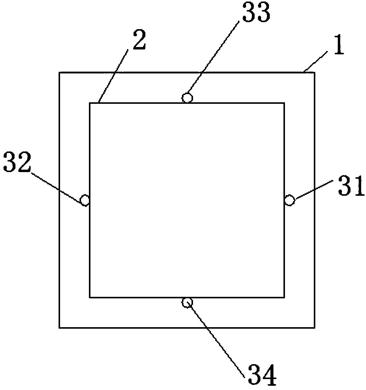
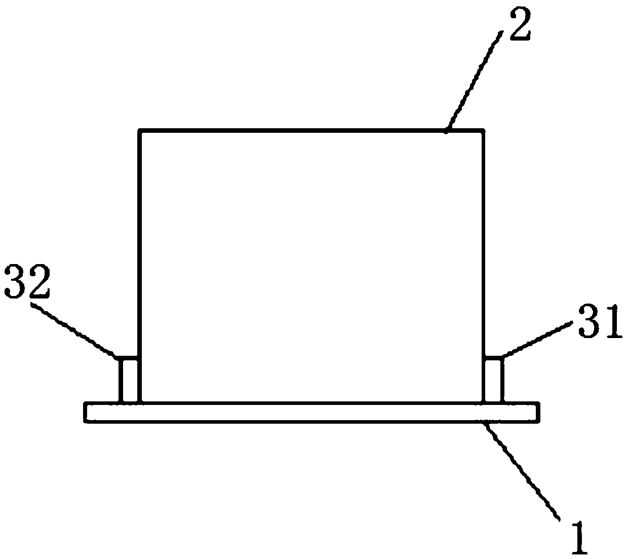
[0037] This embodiment 1 describes a sun tracking device, which is used to track sunlight so that the lighting panel is directly exposed to sunlight. The middle part of the lighting panel is provided with a PCB board 1. The structure of the sun tracking device is as follows figure 1 , figure 2 As shown, it can generally include a shielding block 2, four photodiodes 31, 32, 33, 34 and a comparison control unit, the shielding block 2 is arranged at the center of the PCB board 1, and the shielding block 2 The surface of the surface is black, and four photodiodes are fixed on the PCB board 1 close to the lower part of the shielding block 2, and the four photodiodes 31, 32, 33, 34 are respectively connected with the comparison control unit and fed back The generated electrical signal is compared with the control unit to comprehensively process the data of the four photosensitive diodes 31, 32, 33, 34 and send a control signal to the driving system that drives the movement of the d...

Embodiment 2

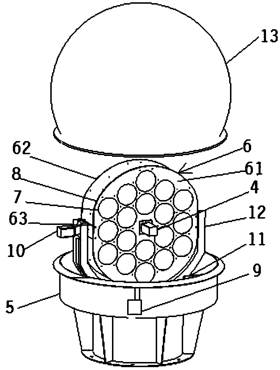
[0044] This embodiment provides a fiber optic sunlight lighting system, such as image 3 As shown, it includes a daylighting panel 6, which is provided with several condenser lenses 7, and the several condenser lenses 7 collect sunlight and then transmit it to the indoor lighting system through an optical fiber. The system can adjust its own azimuth and pitch angle. A sun tracking device 4 is arranged on the daylighting panel 6. The sun tracking device 4 is as described in Embodiment 1. The optical fiber sunlight lighting system is based on the sun tracking device 4 The azimuth and elevation angles of the daylighting panel 6 are adjusted through the drive system as a result of the feedback.

[0045] Preferably, the daylighting panel 6 is arranged on the base 5 through a U-shaped bracket, the drive system includes a first reduction motor 9 and a second reduction motor 10, the first reduction motor 9 is arranged on the base 5, The power shaft 91 is connected to the U-shaped bra...


PUM


Abstract

The invention provides a sun tracking device and an optical fiber sunshine lighting system with the sun tracking device and belongs to the technical field of optical fiber lighting. The sun tracking device adopts the design of four light-sensitive elements combined with a sheltering block, every two light-sensitive elements arranged on opposite sides of the sheltering block are marked as one pair,and then comparison is made according to the size of electrical signals generated by the light-sensitive elements, then embedded program control is performed by a comparison control unit, a driving system is made to rotate the azimuth angle and pitching angle of a daylighting panel, and then the daylighting panel is made to aim at sunlight, then by means of the optical fiber sunshine lighting system with the sun tracking device, the working reliability and moveability of equipment can be improved, meanwhile, by means of initial positions of the marked azimuth angle and pitching angle, the product daylighting panel position initialization can be facilitated, the adjustment of the equipment is facilitated, and the veracity of sun tracking is further guaranteed.

Description

technical field [0001] The invention relates to the technical field of solar lighting, in particular to a sun tracking device and an optical fiber sunlight lighting system with the same. Background technique [0002] In recent years, due to the continuous development of economic construction, saving energy and protecting the environment has become a major theme in today's society. At present, we are facing many problems such as environmental degradation, global warming, and energy shortage. Among them, finding ways to use renewable green energy has become a hot topic in current research, and it also indicates the future development direction of science and technology. In response to this, the concept of solar fiber optic lighting system was proposed at the end of the 20th century. It combines a series of patented technologies such as sun tracking and lens focusing to greatly increase the brightness of sunlight at the focal point, and guide the light to the Where lighting is...

Claims


Application Information

Patent Timeline
IPC IPC(8): F21S11/00F21V5/04F21V8/00F21V23/00
CPCF21S11/005F21S11/007F21V5/04F21V23/003F21V2200/17
Inventor 柴雄良
Owner 苏州臻翌光电科技有限公司
Learn More