A device used for testing interlaminar interfacial shear strength of a fiber composite material bar

A technology of interfacial shear strength and fiber composite materials, applied in the direction of applying stable shear force to test material strength, measuring devices, and analyzing materials, can solve problems such as unguaranteed, inaccurate test data, and inability to perform tests. Achieve the effect of simple structure, good economy and reliable test data

Active Publication Date: 2018-05-15
HARBIN INST OF TECH
View PDF6 Cites 6 Cited by
  • Summary
  • Abstract
  • Description
  • Claims
  • Application Information

AI Technical Summary

Problems solved by technology

The equipment that has been applied for the interlaminar shear strength of FRP rods first fixes the FRP rods, and then conducts the shear test on the top plate along the longitudinal section where the diameter of the rod body is located. The main problem of this method is that it cannot guarantee The shear section is the section where the diameter is located, and in the process of data processing, the selection of the section is the section where the diameter and height of the rod body are located, resulting in inaccurate test data
On the other hand, for hybrid FRP rods formed by two or more fibers, the interfacial shear strength between fibers is regarded as the weak force interface of the hybrid rod body, which cannot be tested by using the above-mentioned shearing device. There is no effective shear equipment for the above-mentioned interfacial shear strength test

Method used


Image

  • A device used for testing interlaminar interfacial shear strength of a fiber composite material bar
  • A device used for testing interlaminar interfacial shear strength of a fiber composite material bar
  • A device used for testing interlaminar interfacial shear strength of a fiber composite material bar

Examples


Embodiment Construction

[0020] The present invention will be described in further detail below in conjunction with the accompanying drawings: the present embodiment is implemented on the premise of the technical solution of the present invention, and detailed implementation is provided, but the protection scope of the present invention is not limited to the following embodiments.

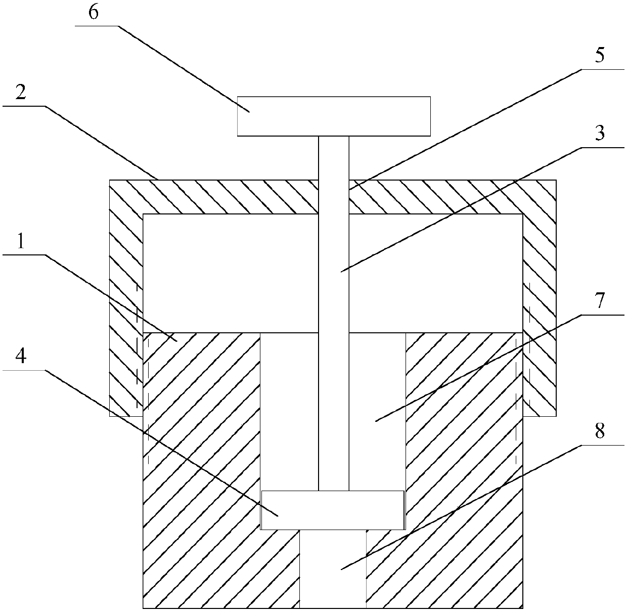
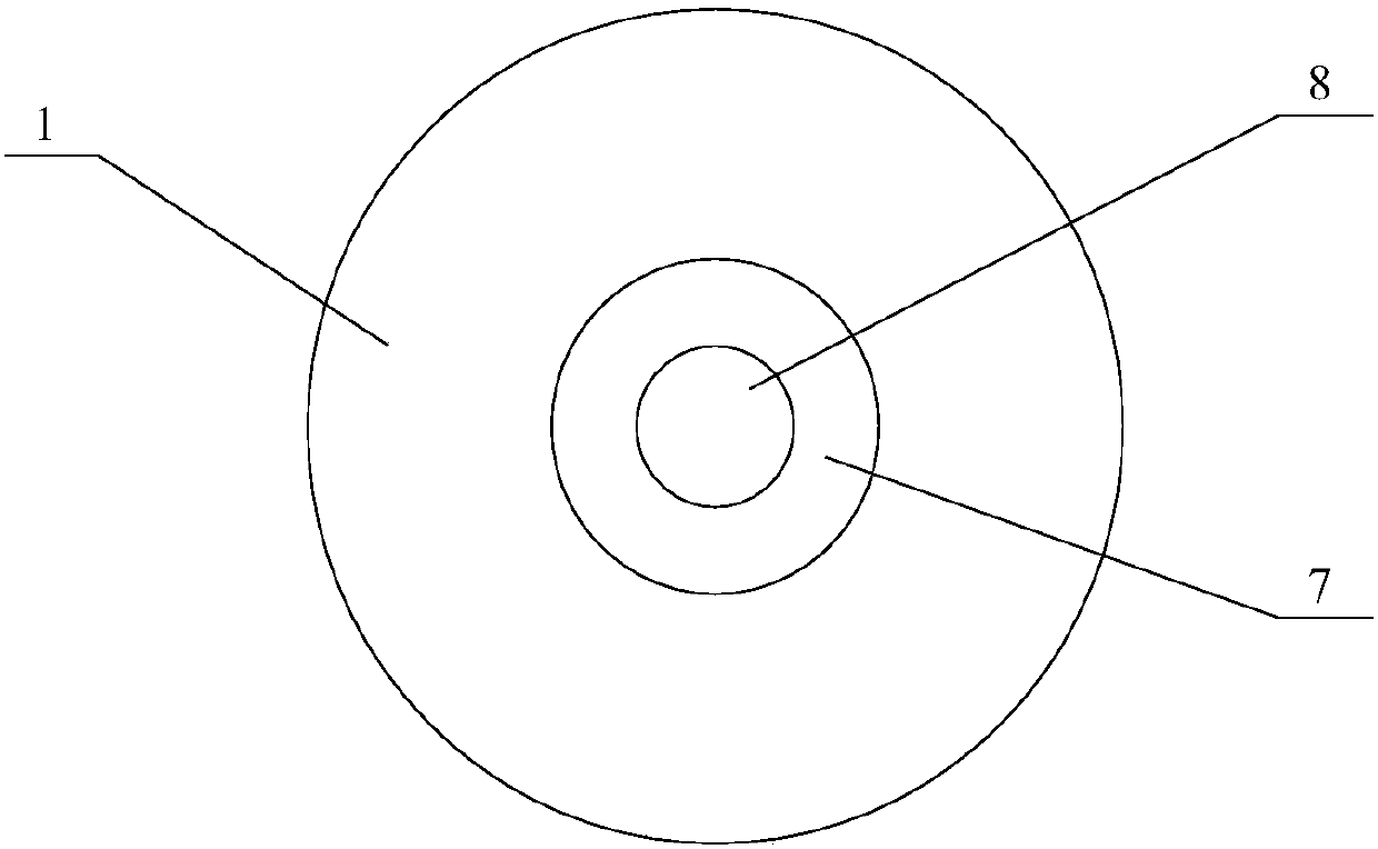
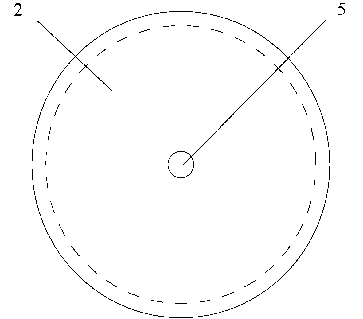
[0021] Such as Figure 1 ~ Figure 4 As shown, a device for testing the interfacial shear strength of fiber composite rods involved in this embodiment includes: a load-bearing base 1, a fixed top cover 2 and a stressed pressure bar 3, and the load-bearing base 1 is provided with a measured rod cavity 7, a through hole 8 is provided on the load-bearing base 1 at the bottom of the measured rod cavity 7, the fixed top cover 2 is threadedly connected with the load-bearing base 1, and the fixed top cover 2 The central position is provided with a pressure rod hole 5, and the stressed pressure rod 3 is connected to the pressure ro...


PUM


Abstract

The invention provides a device used for testing interlaminar interfacial shear strength of a fiber composite material bar, and belongs to the technical field of devices used for testing interlaminarinterfacial shear strength of fiber composite material bars. The center of a bearing pedestal is provided with a cavity for a bar to be tested. The bearing pedestal below the cavity for the bar to betested is provided with a through hole. A fixing top cover is threaded to the bearing pedestal. The center of the fixing top cover is provided with a pressing bar hole. A force bearing pressing bar isconnected to the pressing bar hole in the fixing top cover in an up-down sliding manner. The top end of the force bearing pressing bar is fixed to a force bearing bar top disc. The inner hole diameter of the bearing pedestal and the height of the cavity can be designed according to different fiber bar diameters and testing heights, and shear strength of different cross sections can be obtained byadopting different pressing bar diameters, and therefore the application range of the device is wide. The fixing top cover firmly fixes the force bearing pressing bar to the bearing pedestal throughthreaded connection, thus ensuring vertical forcing applying on a fiber bar in a testing process of the device, and avoiding eccentric force applying.

Description

technical field [0001] The invention relates to a device for testing the interfacial shear strength of fiber composite rod layers, and belongs to the technical field of interfacial shear strength test devices for fiber composite material rod layers. Background technique [0002] Traditional building concrete structural components (beams, slabs, columns) under normal use conditions, the moisture and acid in the air will penetrate into the interior along the concrete surface, thereby corroding the internal steel bars, resulting in a significant decline in the bearing capacity of the structure. On the one hand, it leads to excessive deflection of the structure, on the other hand, more cracks are generated on the surface and inside of the stressed member, which seriously affects the normal use of the member. [0003] In order to solve the decline in the bearing capacity of structural members caused by the corrosion of steel bars, fiber reinforced resin composite (FRP) rods have ...

Claims


Application Information

Patent Timeline
IPC IPC(8): G01N3/24
CPCG01N3/24G01N2203/0025
Inventor 咸贵军李承高
Owner HARBIN INST OF TECH
Why Eureka
Try Eureka