Catalytic rectifying column plate allowing online replacement of catalyst

A catalytic rectification tower and catalyst technology, which is applied in the field of catalytic rectification trays, can solve problems affecting plate efficiency and reaction effect, catalyst wear, large leakage, slow liquid phase replacement, etc., to increase equipment processing capacity, diffusion transmission, etc. Effect of reduced mass resistance, narrow residence time distribution

Active Publication Date: 2018-05-18
WANHUA CHEM GRP CO LTD
View PDF12 Cites 2 Cited by
  • Summary
  • Abstract
  • Description
  • Claims
  • Application Information

AI Technical Summary

Problems solved by technology

Although the structure of the tray is simple, the liquid holding capacity of the sieve tray is limited, the catalyst is unevenly distributed, and the catalyst wears and leaks greatly, which affects the plate efficiency and reaction effect.
Chinese published patent CN01114953 discloses a catalytic rectification tray with a gas riser, the catalyst is scattered at the bottom of the tray, the gas riser is higher than the catalyst height, and gas-liquid mass transfer elements such as float valves, bubble caps, etc. are installed on the gas riser top, because The liquid on the tray flows in one direction in the horizontal direction, the catalyst is unevenly distributed, the rectification efficiency is not high, the reaction liquid cannot pass through the catalyst bed, there are problems such as slow liquid phase replacement, stagnation zone and dead zone, and the reaction effect is affected. influences
Especially for catalytic rectification systems with complex reactions such as serial or parallel reactions, the reaction yield of this type of tray is not good

Method used


Image

  • Catalytic rectifying column plate allowing online replacement of catalyst
  • Catalytic rectifying column plate allowing online replacement of catalyst
  • Catalytic rectifying column plate allowing online replacement of catalyst

Examples


Embodiment 1

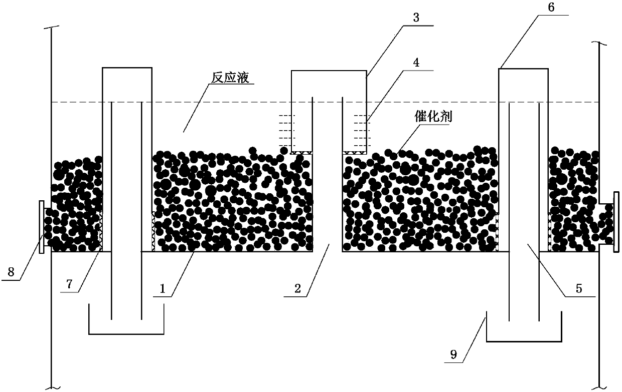
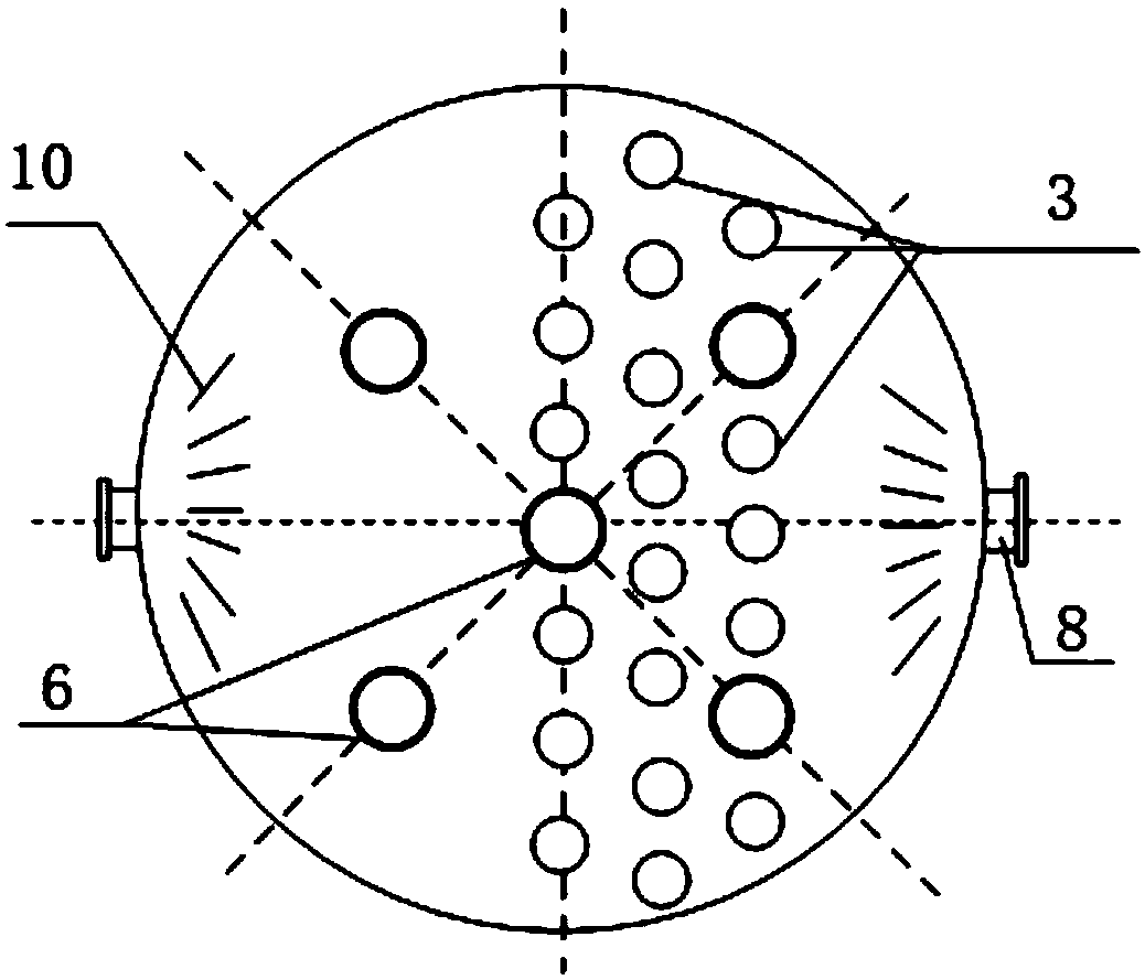
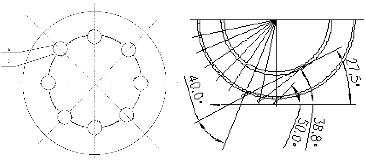
[0039] Such as Figure 1-5 As shown, a catalytic rectification tray that can replace the catalyst on-line includes a tray 1, a plurality of gas-liquid contact elements arranged on the tray, a plurality of suspended downcomers, and a suspended tray below the suspended downcomer. The liquid receiving tray 9 and the catalyst loading and unloading hole 8 for loading and unloading the catalyst on the tray, wherein the suspended downcomer includes the inner downcomer 5 (such as 5 diameters of 65mm) passing through the tray and the inner downcomer that covers the inner downcomer. The outer guide cover 6 of the part above the bottom of the tray, the gas-liquid contact element includes the gas riser 2 installed on the tray and the spray cap 3 (for example, 40 diameters 50mm) installed on the top of the gas riser, the spray cap 3 3 Gas injection holes 4 are provided at the lower end and / or the lower part and below the liquid surface. A deflector 19 is arranged beside the gas injection ...


PUM


Abstract

The invention discloses a catalytic rectifying column plate allowing online replacement of a catalyst. The catalytic rectifying column plate comprises a column tray, a plurality of gas-liquid contactelements and suspended downcomers arranged on the column tray, a suspended receiver tray arranged below the suspended downcomers, and a catalyst handling hole for handling a catalyst on the column tray. A free space formed by the suspended downcomers, the gas-liquid contact elements, the column tray and a column wall is a catalyst filling area; the catalyst is loosely packed in the catalyst filling area; each suspended downcomer comprises an inner downcomer passed through the column tray and an outer guide hood that covers the part, above the bottom of the column tray, of the inner downcomer.The catalytic rectifying column plate has no need for complex packaging of a catalyst; the catalyst is directly loosely packed on the column tray; the catalyst can be replaced online with no need forstopping equipment; the catalyst is distributed evenly; pressure drop of the column tray is low; rectifying efficiency is high. In addition, expensive catalyst packaging material and filling materialare omitted, and the cost can be significantly reduced.

Description

technical field [0001] The invention relates to a new type of equipment for a catalytic rectification process, in particular to a catalytic rectification tray capable of replacing catalysts on-line. technical background [0002] In the traditional chemical production process, the reaction raw materials are generally reacted in the reactor first, and then the reaction products enter the downstream separation process for separation and purification. With the continuous advancement of chemical industry technology, the conventional chemical production process of traditional reaction + separation has more and more disadvantages such as complex process, large equipment investment, and high energy consumption. Various new technologies for process strengthening are emerging. Among them, the reactive distillation technology couples the reaction and distillation separation means, which greatly simplifies the equipment and process, and can significantly improve the yield of equilibrium...

Claims


Application Information

Patent Timeline
Patent Type & Authority Applications(China)
IPC IPC(8): B01D3/32B01J8/02C07C1/24C07C11/09
CPCB01D3/324B01J8/002B01J8/0242C07C1/24C07C11/09Y02P20/10
Inventor 何岩王中华赵一鸣刘俊贤宋明炎乔小飞黎源
Owner WANHUA CHEM GRP CO LTD
Why Eureka
Try Eureka