Movable mounting and dismounting device for mounting and dismounting bottom bolts of large equipment

A technology for bolt disassembly and assembly of large-scale equipment, applied in metal processing equipment, metal processing, manufacturing tools, etc., can solve the problems of reducing work efficiency, noise, vibration, labor intensity, etc., to improve disassembly and assembly efficiency, accurate torque The effect of controlling and reducing labor intensity

Active Publication Date: 2018-05-18
SICHUAN UNIVERSITY OF SCIENCE AND ENGINEERING
View PDF5 Cites 8 Cited by
  • Summary
  • Abstract
  • Description
  • Claims
  • Application Information

AI Technical Summary

Problems solved by technology

Gas-driven wrench has many advantages such as high power, low price, and no pollution. However, the weakness of this type of wrench is also obvious. Large torque, but the hydraulic drive equipment needs to be accompanied by a set of hydraulic devices, the structure is complex, the size is huge, and it is not easy to maintain; the electric drive wrench has many advantages such as high cost performance, large power-to-volume ratio, good control performance, and easy maintenance. It is a high-precision, The development trend of intelligent wrench
Whether it is a gas-driven wrench, a hydraulic-driven wrench or an external power-driven wrench, it is necessary to connect a long power input line (high-pressure air pipe, oil pipe, cable, etc.), and it is inconvenient to constantly drag the heavy power input line during operation, especially in It is

Method used


Image

  • Movable mounting and dismounting device for mounting and dismounting bottom bolts of large equipment
  • Movable mounting and dismounting device for mounting and dismounting bottom bolts of large equipment
  • Movable mounting and dismounting device for mounting and dismounting bottom bolts of large equipment

Examples


Embodiment 1

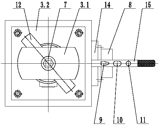
[0035] Such as Figures 1 to 3 , as shown in 6 to 8, a mobile disassembling device for disassembling bolts at the bottom of large-scale equipment, including a mobile frame 1, a jacking mechanism 2, a frame 3, a DC motor 4, a torque control display mechanism 5, and a reducer 6. Sleeve 7, lithium battery power supply 8 and control switch, mobile frame 1 includes mobile frame bottom plate 1.2, mobile frame top plate 1.1 and four columns fixedly connected between the two, frame 3 includes frame bottom plate 3.2, machine The frame top plate 3.1 and four columns fixedly connected between the two, the four corners of the bottom of the mobile frame 1 are equipped with universal wheels 13, so that the dismounting device can move in all directions; the torque control display mechanism 5 is connected with the motor 4, By inputting the torque value in the torque control display mechanism 5, the torque output by the motor 4 can be realized. Here, the torque of the motor 4 is related to its...

Embodiment 2

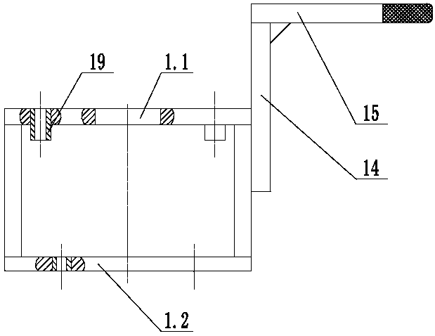
[0042] On the basis of Example 1, such as figure 1 , 3, 5, the jacking mechanism 2 is connected with the frame bottom plate 3.2 through the guide mechanism, the guide mechanism includes at least three guide columns 18 and guide sleeves 19 matched with each guide column 18, the top of the guide column 18 is connected with the frame bottom plate 3.2 Fixed connection, and the connection line between each guide column 18 and the bottom surface of the frame bottom plate 3.2 is not on the same straight line, the guide sleeve 19 is fixedly arranged on the top plate 1.1 of the mobile frame, and the top plate 1.1 of the mobile frame corresponds to each guide sleeve 19. Through holes, the guide sleeve 19 is fixedly installed in the corresponding through hole, and the guide column 18 passes through the corresponding guide sleeve 19 to guide the rise or fall of the frame 3; the jacking mechanism 2 is specifically an electric push rod, lithium The battery power supply 8 can provide power ...

Embodiment 3

[0044] On the basis of Example 2, such as figure 1 and 4 As shown, an adsorption positioning mechanism is fixedly arranged on the mobile frame base plate 1.2, and the adsorption positioning mechanism includes an electromagnetic chuck 23, a fixed rod 24, a return spring 25 and a baffle plate 26. The lithium battery power supply 8 can provide power for the electromagnetic chuck 23, and the mobile frame Bottom plate 1.2 is provided with through hole, and fixed rod 24 passes through this through hole, and the bottom end of fixed rod 24 is fixedly connected with electromagnetic sucker 23, and the top end is fixedly connected with baffle plate 26, and back-moving spring 25 is sleeved on the fixed rod 24, and its upper end withstands The bottom surface and the lower end of the baffle plate 26 withstand the top surface of the mobile frame base plate 1.2, when the electromagnetic chuck 23 is energized, it can absorb the ground steel plate 27 of the workshop, so that the dismounting dev...


PUM


Abstract

The invention relates to the technical field of mounting and dismounting of mechanical equipment and discloses a movable mounting and dismounting device for mounting and dismounting bottom bolts of large equipment. The movable mounting and dismounting device comprises a moving frame, a jacking mechanism, a rack, a motor, a torque control display mechanism, a speed reducer, a sleeve, a lithium battery power supply and control switches; the torque control display mechanism is connected with the motor and controls the motor to output the torque; the jacking mechanism is fixedly arranged on a bottom plate of the moving frame; the rack is located above a top plate of the moving frame; the jacking mechanism is connected with the rack, supports the rack and controls the rack to rise or fall; themotor is arranged on a bottom plate of the rack; an output shaft of the motor is connected with the speed reducer; an output shaft of the speed reducer is connected with the sleeve; the motor drives the sleeve to rotate through the speed reducer; the lithium battery power supply supplies power to the motor and the jacking mechanism; and the control switches include a forward/reverse rotation switch, a rising/falling switch and a rotation switch. The device is moved under the large equipment conveniently by a worker, is safe and effort-saving to operate and is high in efficiency, a power inputline is not required to be dragged, passing of other equipment is not affected, and accurate control on the torque is realized.

Description

technical field [0001] The invention relates to the technical field of disassembly and assembly of mechanical equipment, in particular to a mobile disassembly and assembly device used for disassembly and assembly of bolts at the bottom of large-scale equipment. Background technique [0002] The bottom of some large-scale equipment is often designed with many bolt links, such as the bolts on the bottom ring of the water turbine used to fix multiple sets of sealing combinations, some as many as 100 or so; There are as many as 30 bolts per car. These bolted connections often need to be installed, tightened or disassembled during equipment assembly and maintenance, and the tightening torque of the bolts must comply with relevant industry standards. [0003] Faced with the bolts at the bottom of this large-scale equipment, at present, the main method in China is to manually drill under the equipment and hold wrenches of various driving modes upward for disassembly and assembly o...

Claims


Application Information

Patent Timeline
IPC IPC(8): B23P19/06
CPCB23P19/06B23P19/066
Inventor 付鸽侯书增张建平胡勇补友华
Owner SICHUAN UNIVERSITY OF SCIENCE AND ENGINEERING
Why Eureka
Try Eureka