
Electronic product carton sealing machine

A technology for electronic products and carton sealing machines, applied in packaging sealing/fastening, external support, transportation packaging, etc., can solve the problems that the conveying part cannot be deformed, the specifications of the packaging boxes are different, and the sealing efficiency of the carton sealing machine is reduced. Quality, the effect of improving sealing efficiency

Inactive Publication Date: 2018-05-18
重庆市长寿区普爱网络科技有限公司
View PDF6 Cites 5 Cited by
  • Summary
  • Abstract
  • Description
  • Claims
  • Application Information

AI Technical Summary

Problems solved by technology

[0003] The existing technology has the following technical problems: 1. When the specifications of the packaging boxes to be sealed are different, the transmission part cannot deform according to the width of the packaging box, and the packaging box sealed by the sealing machine is not beautiful, and the packaging box is also unsightly when glued. It is easy to shake, which reduces the sealing efficiency of the box sealer; 2. The existing box sealer uses a smoothing device to smooth the two side panels and two end panels of the packaging box, and then uses tape to seal, and gaps are prone to appear at the seal , affecting the quality of the box after sealing

Method used


Image

  • Electronic product carton sealing machine
  • Electronic product carton sealing machine
  • Electronic product carton sealing machine

Examples


Embodiment Construction

[0035] The present invention will be described in further detail below by means of specific embodiments:

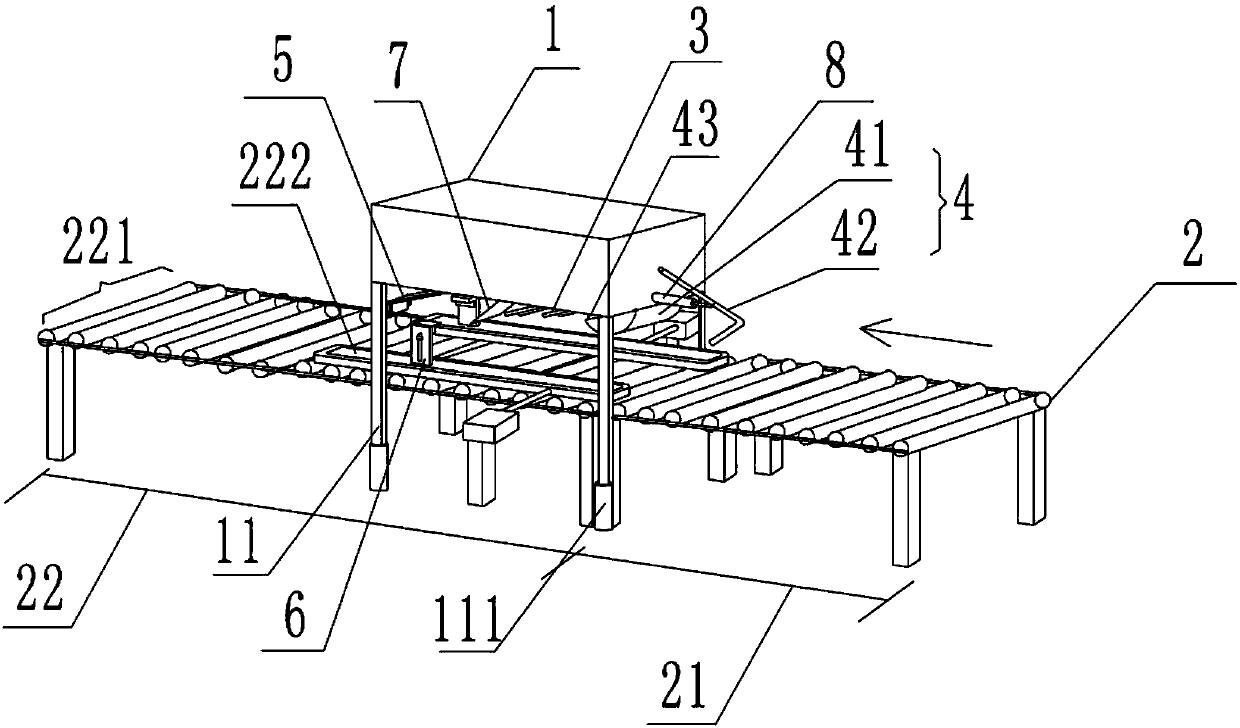
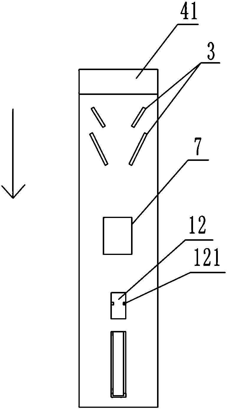
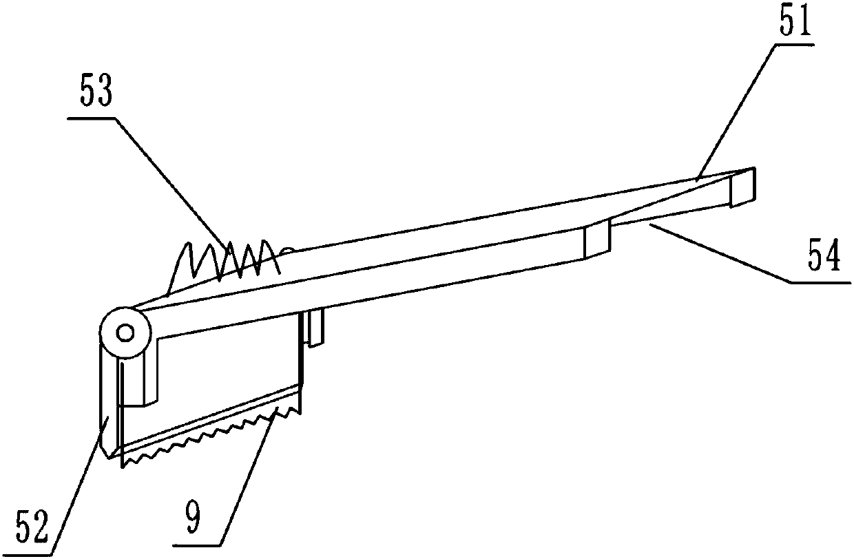
[0036]The reference signs in the drawings of the description include: frame body 1, telescopic rod 11, storage slot 12, support shaft 121, transmission part 2, front transmission part 21, rear transmission part 22, transmission plane 221, slide bar 222, eight Glyph smoothing rod 3, end plate smoothing part 4, front smoothing plate 41, rear folding rod 42, compression spring 43, adhesive tape sticking part 5, branch plate 51, scraper 52, elastic member 53, groove 54, extrusion Part 6, L-shaped extrusion plate 61, T-shaped convex strip 611, swivel 612, spring 613, pole 62, strip groove 621, limit groove 622, limit part 7, hydraulic cylinder 8, scotch tape 9 , Front end plate A, rear end plate B, left side plate C, right side plate D, corner 10.

[0037] Such as figure 1 and figure 2 As shown, a sealing machine for electronic products includes a frame body 1, a transmiss...


PUM


Abstract

The invention relates to the technical field of forward movement mechanisms, in particular to an electronic product carton sealing machine. The electronic product carton sealing machine comprises a machine frame body, a conveying part, a side plate flattening part, an end plate flattening part and an adhesive tape sticking part. The end plate flattening part, the side plate flattening part and theadhesive tape sticking part are all sequentially arranged in the conveying direction of the conveying part. Telescoping parts are arranged at the bottom of the machine frame body. The conveying partcomprises a rear conveying part body and a front conveying part body which is formed by a chain drive roller bed. The rear conveying part body comprises a conveying rack. The upper surface of the conveying rack is provided with a conveying plane which is composed of a plurality of cylinders, and the two sides of the cylinders are connected with the two sides of the conveying rack separately. The conveying plane is provided with sliding bars which can move oppositely along the conveying plane and are used for clamping packing boxes. A conveying belt is arranged on the side faces of the slidingbars. The sliding bars are further provided with squeezing parts used for squeezing the upper portions of the packing boxes. A limiting part used for preventing flattened side plates and end plates ofthe packing boxes from being warped upwards is further arranged at the bottom of the machine frame body. According to the scheme, the packing boxes of various specifications can be sealed and gaps inthe sealed positions can be prevented.

Description

technical field [0001] The invention relates to the technical field of forward-moving mechanisms, in particular to an electronic product box sealing machine. Background technique [0002] After the production of electronic products is completed, the box is generally sealed; and the packaging box is the most widely used packaging product. The mass-produced electronic products are all operated on an assembly line, and mechanical equipment is equipped at each corresponding part of the assembly line, thereby reducing the labor intensity of workers. It can also improve production efficiency. The last end of the assembly line is equipped with sealing equipment to seal and package the products for easy storage and transportation. The existing packaging boxes all include a box body, which is provided with two side panels and two end panels; generally, after the electronic product is put into the packaging box, the packaging box will be sealed, and the common packaging boxes are sea...

Claims


Application Information

Patent Timeline
Patent Type & Authority Applications(China)
IPC IPC(8): B65B51/06
CPCB65B51/06
Inventor 李天翼
Owner 重庆市长寿区普爱网络科技有限公司
Learn More