A pressure control system for a valve-controlled asymmetric cylinder and its control method

An asymmetric cylinder and pressure control technology, applied in pressure control systems and pressure control fields, can solve the problems of electro-hydraulic servo systems that are difficult to work normally, difficult to establish mathematical models, hidden safety hazards, etc., and achieve simple and effective control ideas and simple structure , the effect of energy saving efficiency

Inactive Publication Date: 2019-07-23
XIAN UNIV OF TECH
View PDF12 Cites 0 Cited by
  • Summary
  • Abstract
  • Description
  • Claims
  • Application Information

AI Technical Summary

Problems solved by technology

However, this system must form a double closed-loop feedback loop through position, speed and pressure sensors on the basis of accurate modeling to achieve the purpose of controlling the system pressure, but the hydraulic system is a typical nonlinear, time-varying system, and the system has time-varying parameters As well as the uncertainty caused by various external disturbances, it is difficult to establish an accurate mathematical model
Even if the structure and parameters of the hydraulic part are determined, the performance of the system depends on the system control part, which puts high demands on the system control part. If there is a problem in the control part, it will make the entire electro-hydraulic servo system difficult to work normally. Bring safety hazards and economic losses to practical engineering applications

Method used


Image

  • A pressure control system for a valve-controlled asymmetric cylinder and its control method
  • A pressure control system for a valve-controlled asymmetric cylinder and its control method
  • A pressure control system for a valve-controlled asymmetric cylinder and its control method

Examples


Embodiment Construction

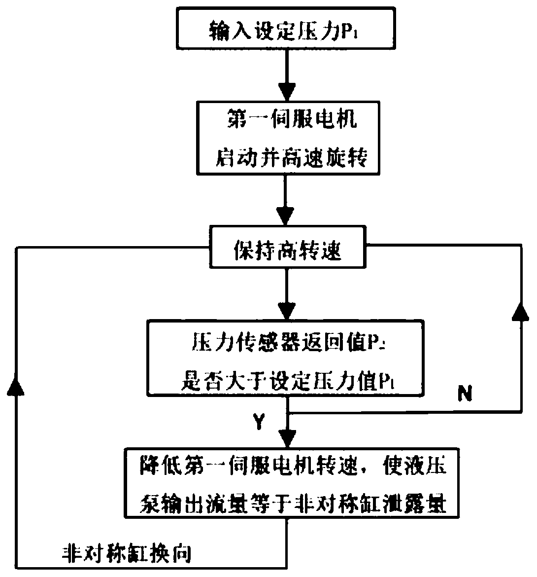
[0023] The present invention will be described in detail below in conjunction with the accompanying drawings and specific embodiments.

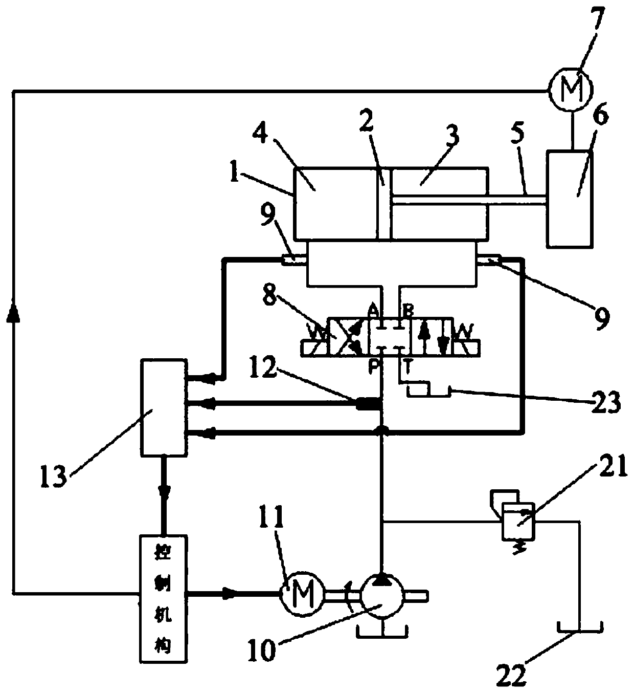
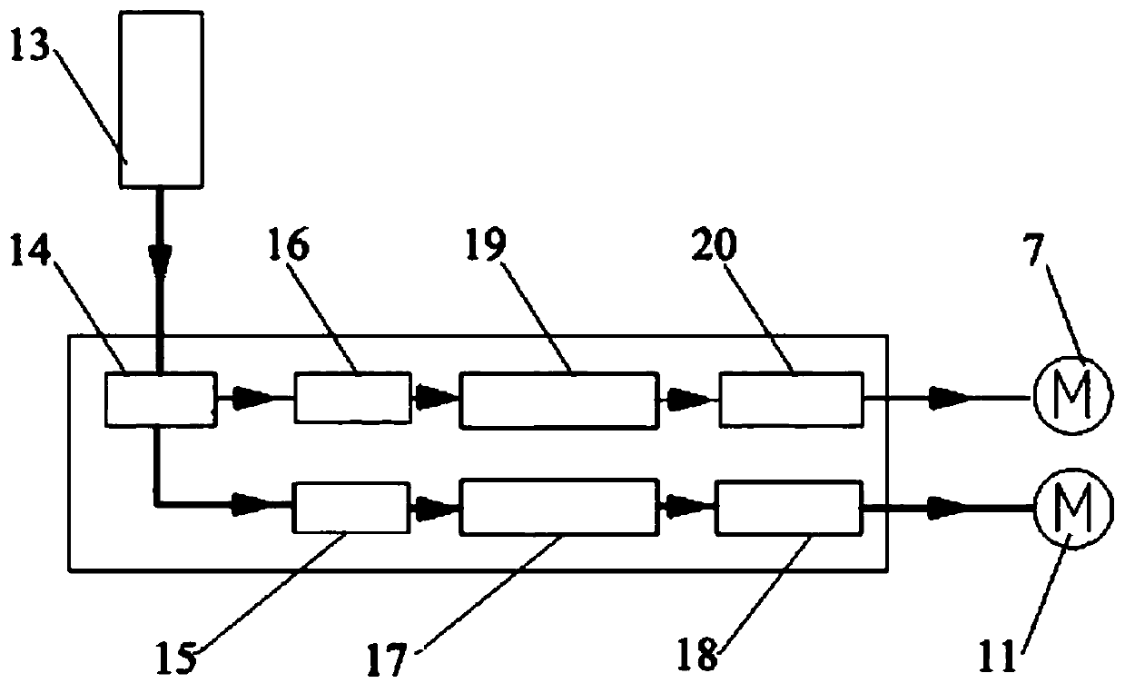
[0024] The invention provides a pressure control system for a valve-controlled asymmetric cylinder, such as figure 1 As shown, the high-pressure oil at the outlet of the hydraulic pump 10 is first connected to the inlet of the relief valve 21, and then the inlet of the relief valve 21 is connected to the P port of the three-position four-way electromagnetic reversing valve 8, and at the inlet of the relief valve 21 The signal collection end of the pressure sensor 12 is connected between the P port of the three-position four-way electromagnetic reversing valve 8, and the outlet T of the three-position four-way electromagnetic reversing valve 8 and the outlet of the overflow valve 21 are connected back to the fuel tank. Port A of the three-position four-way electromagnetic reversing valve 8 is connected to the rodless chamber 4 of the asymmetri...


PUM


Abstract

The invention discloses a pressure control system of a valve-controlled asymmetric cylinder. The pressure control system comprises an asymmetric cylinder, a piston and a piston rod are arranged in theasymmetric cylinder in a cooperating mode, one end of the piston rod extends out of the asymmetric cylinder and is connected with a three-jaw chuck, and the three-jaw chuck is connected with a secondservo motor; the positions where a rod cavity and a rodless cavity are located, of the asymmetric cylinder jointly communicate with a three-position four-way electromagnetic directional valve throughpipelines, furthermore a temperature sensor is arranged on each connecting pipeline, the three-position four-way electromagnetic directional valve further communicates with a hydraulic pump through apipeline, a pressure sensor is arranged on the connecting pipeline, and the pressure sensor and the two temperature sensors are jointly connected with a signal acquisition instrument; and the hydraulic pump is connected with a first servo motor, and the signal acquisition instrument, the first servo motor and the second servo motor are jointly connected with a control mechanism. According to thepressure control system of the valve-controlled asymmetric cylinder, the pressure of the electro-hydraulic servo system can be simply and effectively controlled, and the optimal energy-saving purposecan be achieved. The invention further discloses a method for carrying out pressure control by adopting the system.

Description

technical field [0001] The invention belongs to the technical field of fluid transmission and control, and in particular relates to a pressure control system of a valve-controlled asymmetric cylinder, and also relates to a pressure control method using the system. Background technique [0002] The electro-hydraulic servo system has the characteristics of fast response, high rigidity, compact structure, small inertia, and high precision. It is now widely used in industrial machinery, walking machinery, aerospace, ships, and marine development projects. In the electro-hydraulic servo system, the valve-controlled asymmetric cylinder is widely used because of its simple structure, low cost, small working space and large bearing capacity. Pressure is one of the basic control parameters of the electro-hydraulic servo system, and it is extremely important to study the pressure control method in the electro-hydraulic servo system to optimize the structure of the electro-hydraulic se...

Claims


Application Information

Patent Timeline
Patent Type & Authority Patents(China)
IPC IPC(8): F15B11/08F15B13/044F15B19/00F15B21/02B23B31/30
CPCB23B31/302F15B11/08F15B13/044F15B19/00F15B21/02F15B2211/20515F15B2211/405F15B2211/857
Inventor 高峰武鹏飞罗莹莹李艳张东亚税琳棋段继豪
Owner XIAN UNIV OF TECH
Why Eureka
Try Eureka