Design-improved permanent magnetic synchronous servo motor structure

A servo motor, permanent magnet synchronous technology, applied in synchronous motors with static armatures and rotating magnets, electrical components, electromechanical devices, etc., can solve problems such as increasing workload, aggravating vibration, affecting motor efficiency and accuracy, etc. , to achieve the effect of reducing the number of parts, ensuring the installation accuracy, and ensuring the accuracy requirements

Inactive Publication Date: 2018-05-18
SHANGHAI AEROSPACE CONTROL TECH INST
View PDF8 Cites 5 Cited by
  • Summary
  • Abstract
  • Description
  • Claims
  • Application Information

AI Technical Summary

Problems solved by technology

The end cover and the shell are fastened by bolts, which obviously cannot provide enough external force to suppress these vibration sources, which will cause local vibration to exceed the standard and affect the working accuracy of the motor.
In addition, with the increase of working life and the influence of axial vibration, a gap will gradually form between the end cover and the housing, which will aggravate the degree of vibration and even generate noise, which seriously affects the normal operation of the motor
Therefore, when assembling the motor, it is also necessary to consider the strength of the bolts, the axial load that can be borne, etc., which increases a lot of workload and affects the overall strength of the motor.
On the whole, although the current manufacturing process has improved the production efficiency of the motor, it has added some complicated problems, which affect the working efficiency and precision of the motor.

Method used


Image

  • Design-improved permanent magnetic synchronous servo motor structure

Examples


Embodiment Construction

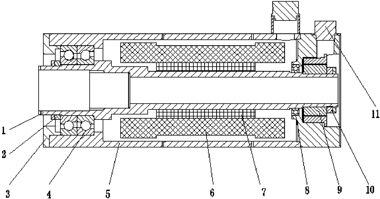
[0016] The present invention will be further described in conjunction with the accompanying drawings.

[0017] An improved design of permanent magnet synchronous servo motor structure, such as figure 1 As shown, it includes hollow rotor shaft 1, lock nut 2, bearing end cover 3, angular contact ball bearing installed back to back 4, shell 5 with integrated design of end cover and shell, stator 6, permanent magnet 7, deep groove ball bearing 8. Resolver 9, resolver lock nut 10, connector 11. The rotor shaft 1 adopts a hollow structure, and the permanent magnet 7 is attached to the rotor shaft 1 . The angular contact ball bearing 4 is installed on one end of the rotor shaft 1, and the outer circle is matched with the inner hole of the housing 5; the rotor shaft 1 is provided with a shaft shoulder and threaded, and the lock nut 2 is used to fix the inner ring of the bearing 4; the inner circumference of the housing 5 is provided The shoulder, the bearing end cover 3 are used to ...


PUM


Abstract

The invention relates to a design-improved permanent magnetic synchronous servo motor structure. The design-improved permanent magnetic synchronous servo motor structure comprises a rotor shaft (1), abearing end cover (3) and an angular contact ball bearing (4), wherein the rotor shaft (1) is mounted in a casing (5), a permanent magnet (7) is mounted at the central portion of the rotor shaft (1),a stator (6) is sleeved with the permanent magnet (7) and is in the casing (5), the angular contact ball bearing (4) is mounted at one end of the rotor shaft (1), the bearing end cover (3) is mountedat one end of the casing (5), an outer ring of the angular contact ball bearing (4) is fixed, a deep groove ball bearing (8) and a rotary transformer (9) are sequentially mounted at the other end ofthe rotor shaft (1), the rotary transformer (9) is close to an end portion of the rotor shaft (1), and a socket connector (11) is mounted on the casing (5). The design-improved permanent magnetic synchronous servo motor structure is advantaged in that coaxiality of a center hole of the end cover and the casing is guaranteed, external structure strength of a motor is improved, and a problem of rotor skewing caused by coaxiality of a split type motor and a local vibration problem caused by bolt connection are solved.

Description

technical field [0001] The invention relates to a servo mechanism of a launch vehicle control system, in particular to an improved design of a permanent magnet synchronous servo motor structure. Background technique [0002] At present, the mechanical structure of the servo motor is obtained by assembling various discrete parts. Among them, the motor end cover is an important part in the motor structure. It connects the stator and rotor through bearings and plays a vital role in the quality of the motor. . Its structural design not only affects the mechanical strength and appearance of the motor, but also affects the processing and overall assembly process of the motor. [0003] In the current common motor mechanism, the end cover and the motor housing are processed separately, and then the two are assembled by bolts to form the external structure of the motor. Such a solution improves the production efficiency of the motor, but at the same time brings many disadvantages. ...

Claims


Application Information

Patent Timeline
Patent Type & Authority Applications(China)
IPC IPC(8): H02K21/14H02K7/00H02K29/06H02K7/08H02K5/06H02K5/24H02K7/10
CPCH02K21/14H02K5/06H02K5/24H02K7/003H02K7/085H02K7/10H02K29/06
Inventor 冒娟娟崔业兵曾凡铨宋树伟周阳
Owner SHANGHAI AEROSPACE CONTROL TECH INST
Why Eureka
Try Eureka