Optical proximity correction-based method for reducing fluctuation of grid

An optical proximity effect and gate technology, applied in optics, optomechanical equipment, microlithography exposure equipment, etc., can solve problems such as large correction error of spacer terminals, affecting product performance, and gate size fluctuations.

Active Publication Date: 2018-05-22
SHANGHAI HUALI MICROELECTRONICS CORP
View PDF6 Cites 1 Cited by
  • Summary
  • Abstract
  • Description
  • Claims
  • Application Information

AI Technical Summary

Problems solved by technology

[0009] Mask Rule Constraint is also an important factor affecting OPC accuracy, such as image 3 In the case shown, in addition to the influence of the corner rounding effect on the gate area, the restriction of the mask plate rules also leads to a large correction error at the Space End. These OPC results eventually lead to fluctuations in the gate size and affect product performance

Method used


Image

  • Optical proximity correction-based method for reducing fluctuation of grid
  • Optical proximity correction-based method for reducing fluctuation of grid
  • Optical proximity correction-based method for reducing fluctuation of grid

Examples


Embodiment Construction

[0051] The technical solutions in the embodiments of the present invention will be clearly and completely described below in conjunction with the accompanying drawings in the embodiments of the present invention. Obviously, the described embodiments are only a part of the embodiments of the present invention, rather than all the embodiments. Based on the embodiments of the present invention, all other embodiments obtained by those of ordinary skill in the art without creative work shall fall within the protection scope of the present invention.

[0052] It should be noted that the embodiments of the present invention and the features in the embodiments can be combined with each other if there is no conflict.

[0053] The present invention will be further described below with reference to the drawings and specific embodiments, but it is not a limitation of the present invention.

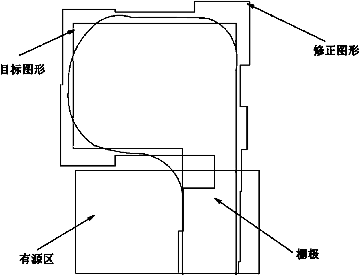
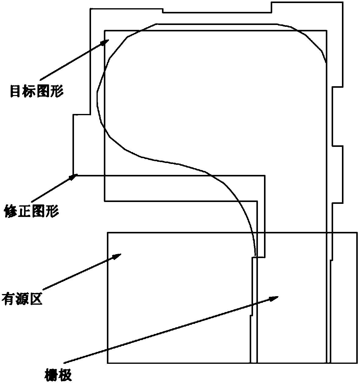
[0054] The technical solution of the present invention includes a method for reducing grid fluctuation ba...


PUM


Abstract

The invention provides an optical proximity correction-based method for reducing fluctuation of a grid. The method is applied to a photoetching process, a target pattern is provided, and a pattern edge of the target pattern is cut to form a mobile pattern segment. The method comprises the following steps of S1, performing simulation exposure on the target pattern to obtain an edge error of the target pattern; S2, moving the pattern segment according to the edge error, and executing the step S3 after the moved target pattern reaches a preset value; S3, stopping moving the pattern segment, judging whether the moving pattern segment is an interval terminal or not, and executing the step S4 if the moving pattern segment is the interval terminal; S4, continuously moving the interval terminal after moving according to the distance between the current pattern segment and a grid; and S5, fixing the current pattern segment to form a final correction pattern. The method provided by the technicalscheme has the beneficial effects that the size fluctuation of the grid can be effectively reduced during the correction process, and the product performance can be improved.

Description

Technical field [0001] The invention relates to the field of semiconductor preparation, and in particular to a method for reducing grid fluctuations based on optical proximity effect correction. Background technique [0002] In the field of sub-wavelength lithography process, RET (Resolution Enhancement Technology) technology has become an important guarantee for improving the resolution of graphics and enhancing the stability of the lithography process. In the process of continuously seeking the limit of 193nm lithography resolution capability, some enhancement methods of 193nm lithography technology such as immersion lithography and double exposure technology have been applied in semiconductor manufacturing. However, before finding a suitable fundamental alternative solution, For example, EUV (Extreme Ultraviolet Light) is commercialized, OPC Optical Proximity Correction, and optical proximity correction. ) Is still a key technology required for advanced semiconductor manufact...

Claims


Application Information

Patent Timeline
Patent Type & Authority Applications(China)
IPC IPC(8): G03F7/20
CPCG03F7/70441G03F7/70491
Inventor 何大权胡青魏芳
Owner SHANGHAI HUALI MICROELECTRONICS CORP
Why Eureka
Try Eureka