Heat radiation type electric switch cabinet

An electrical switch and heat dissipation technology, which is applied in the field of electrical equipment, can solve problems such as burnout of electrical components, fire, and emergency repairs in a short time, and achieve the effects of preventing excessive temperature of the cabinet, facilitating maintenance, and facilitating observation

Inactive Publication Date: 2018-05-22
安徽国晖电气科技有限公司
View PDF4 Cites 3 Cited by
  • Summary
  • Abstract
  • Description
  • Claims
  • Application Information

AI Technical Summary

Problems solved by technology

[0002] The switchgear is a cabinet that controls electrical equipment. The switchgear is mainly equipped with electrical components such as wires and cables, switch circuit breakers, and transfer switches. In some high-temperature areas or hot summers, the heat dissipation of the switchgear is particularly important. There are often cases of electrical components being burned out due to high temperature in the area. In severe cases, it will cause fires and serious economic losses; therefore, it is very necessary to effectively dissipate heat inside the switchgear; Emergency repairs, how to facilitate maintenance workers to quickly repair, is also a problem that needs to be solved

Method used


Image

  • Heat radiation type electric switch cabinet
  • Heat radiation type electric switch cabinet
  • Heat radiation type electric switch cabinet

Examples


Embodiment Construction

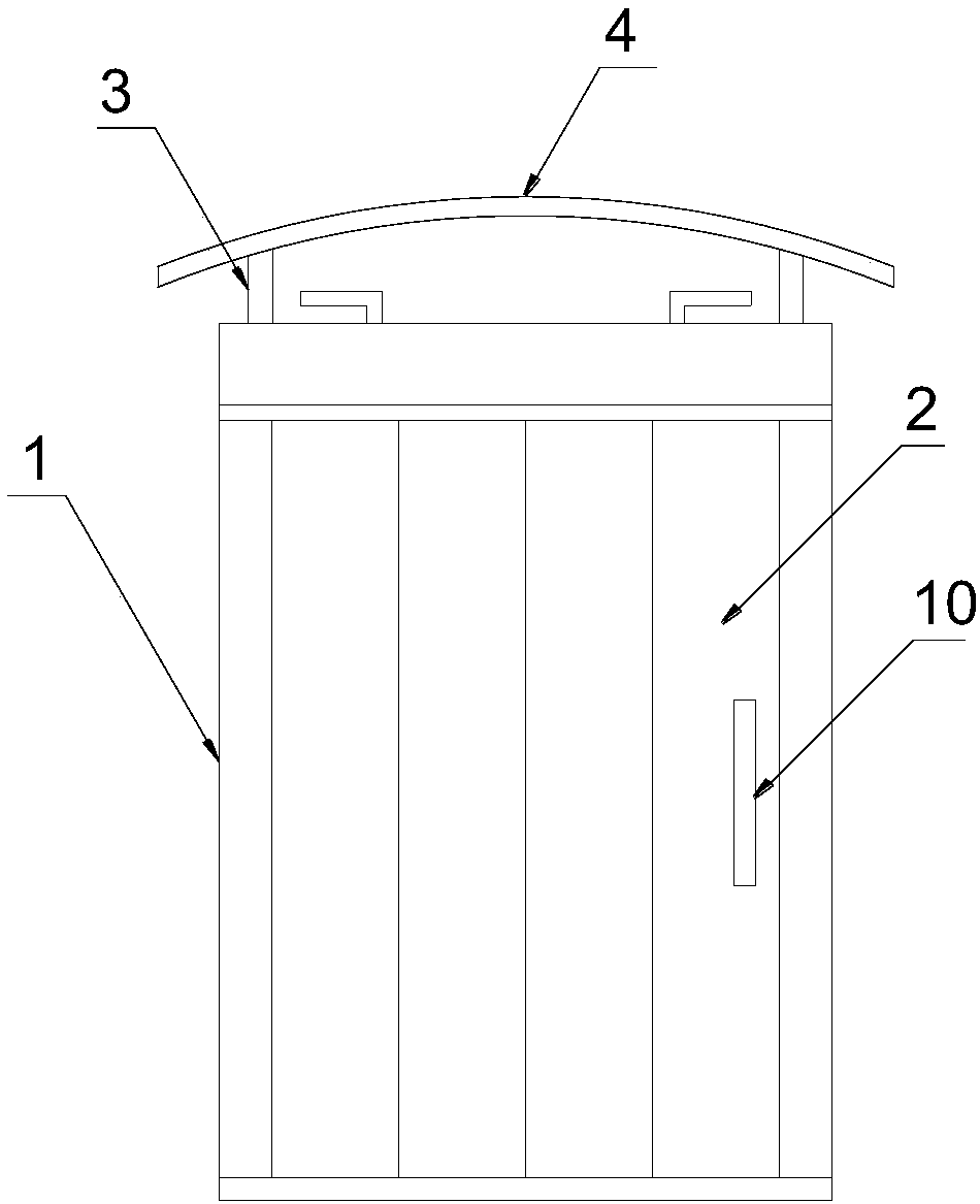
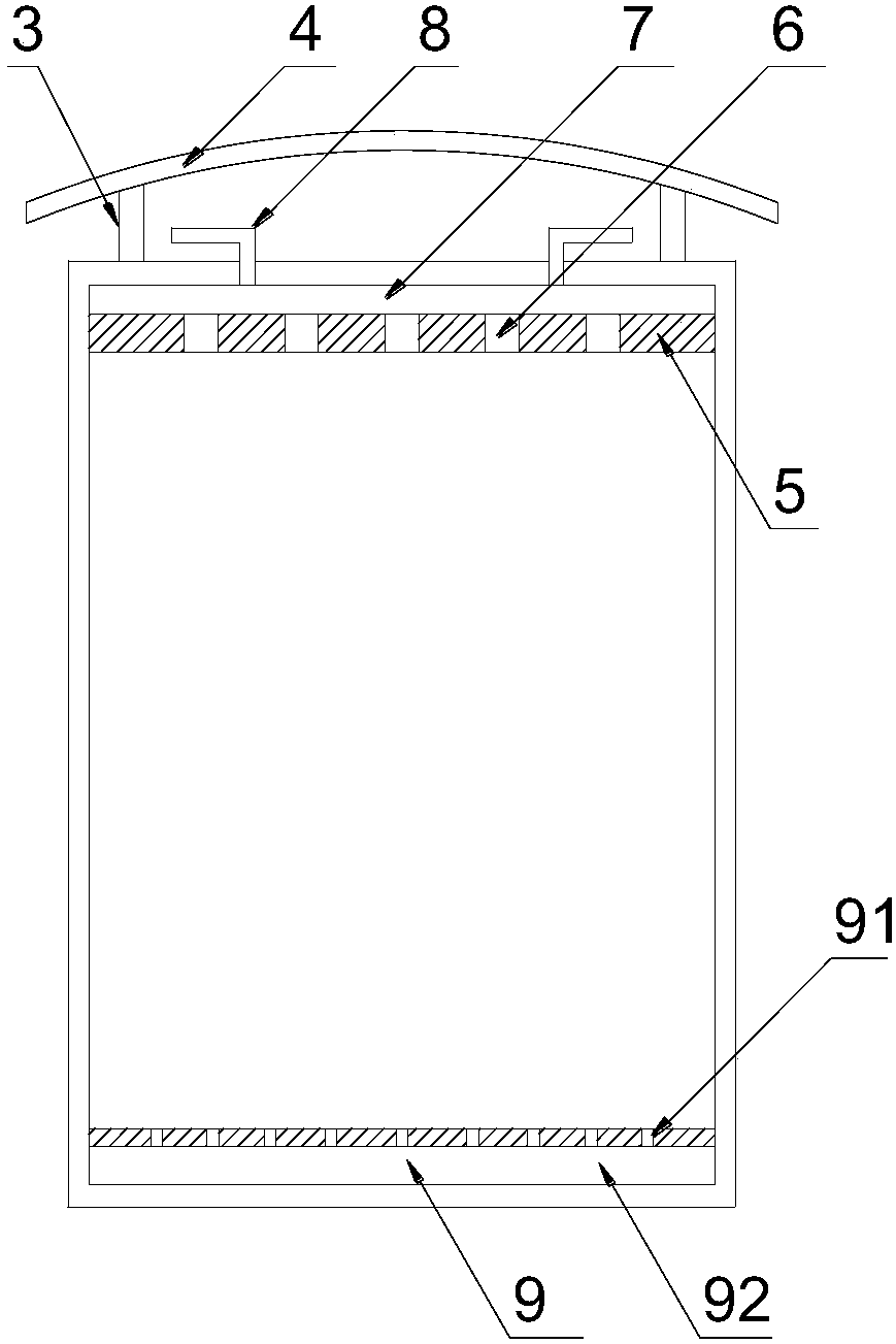
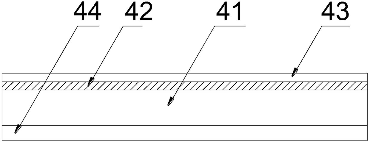
[0019] like Figure 1-5 as shown, figure 1 It is the front schematic diagram of the heat-dissipating type electric switchgear that the present invention proposes, figure 2 It is a schematic diagram of the internal structure of the heat-dissipating electrical switchgear proposed by the present invention, image 3 It is the structural representation of the sun visor in the heat dissipation electric switchgear proposed by the present invention, Figure 4 It is a schematic diagram of closing the folding door in the heat-dissipating electrical switchgear proposed by the present invention, Figure 5 It is a schematic diagram of opening the folding door in the heat-dissipating electrical switchgear proposed by the present invention.

[0020] refer to Figure 1-5 , a kind of heat-dissipating electric switchgear that the present invention proposes, comprises cabinet body 1, folding door and sun visor 4; Cabinet body 1 top is provided with bracket 3, and sun visor 4 is installed ab...


PUM


Abstract

The invention discloses a heat radiation type electric switch cabinet. The heat radiation type electric switch cabinet includes a cabinet body, a folding door and a sun shield plate, wherein a supportis arranged at the top of the cabinet body; the sun shield plate is arranged above the support; in the vertical direction, the projection area of the sun shield plate is greater than the projection area of the cabinet body; the body of the sun shield plate is a hollow metal plate, and a layer of reflective membrane is arranged above the body; a water proof layer is arranged at the outer side of the reflective membrane; a heat sink is arranged at the bottom of the body of the sun shield plate; a separator plate is internally arranged above the cabinet; a plurality of ventilating holes are formed uniformly in the separator plate; a ventilating layer is formed between the upper part of the separator plate and the top of the cabinet body; the ventilating layer is internally filled with filtercotton; ventilating tubes are arranged at the outer side of the top of the cabinet body, and are horizontally arranged L-shaped; the vertical segment of each ventilating tube penetrates through the cabinet body to communicate with the ventilating layer, and the horizontal segment of each ventilating tube is located below the sun shield plate at the outer side of the top of the cabinet body; the folding door is arranged at the front side of the cabinet body, and is formed by successive connection of multiple door plates; and a door handle is arranged on the folding door. The heat radiation type electric switch cabinet has the advantages of being good in the sunshade and rainproof effect, being good in the heat radiation and ventilation effect of the cabinet body, and being convenient for maintenance.

Description

technical field [0001] The invention relates to the field of electrical equipment, in particular to a heat dissipation type electrical switchgear. Background technique [0002] The switchgear is a cabinet that controls electrical equipment. The switchgear is mainly equipped with electrical components such as wires and cables, switch circuit breakers, and transfer switches. In some high-temperature areas or hot summers, the heat dissipation of the switchgear is particularly important. There are often cases of electrical components being burned out due to high temperature in the area. In severe cases, it will cause fires and serious economic losses; therefore, it is very necessary to effectively dissipate heat inside the switchgear; Emergency repairs, how to facilitate maintenance workers to quickly repair, is also a problem that needs to be solved. Contents of the invention [0003] In order to solve the technical problems in the background technology, the present inventio...

Claims


Application Information

Patent Timeline
Patent Type & Authority Applications(China)
IPC IPC(8): H02B1/56H02B1/28H02B1/30
CPCH02B1/565H02B1/28H02B1/30
Inventor 徐家全
Owner 安徽国晖电气科技有限公司
Why Eureka
Try Eureka