Large torque reduction box for withdrawal and straightening machine

A high-torque, reducer technology, applied in the field of high-torque reducers for tension levelers, can solve the problems of small torque, unable to meet the requirements of continuous casting, unable to take into account the requirements of large speed ratio and large torque, etc.

Inactive Publication Date: 2018-05-25
JIANGSU TAILONG MACHINERY GRP CO CO LTD
View PDF4 Cites 2 Cited by
  • Summary
  • Abstract
  • Description
  • Claims
  • Application Information

AI Technical Summary

Problems solved by technology

[0002] The reducer used on the metallurgical continuous casting tension leveling machine is generally composed of a box body, a box cover, a flange, an input shaft, a hollow shaft and a gear transmission mechanism. The traditional cylindrical gear transmission mechanism cannot take into account the high speed ratio and high torque requirements of its use. However, the existing bevel gear set input can meet the speed ratio requirements, but the final torque is relatively small, and cannot meet the increasingly high continuous casting requirements.

Method used


Image

  • Large torque reduction box for withdrawal and straightening machine

Examples


Embodiment Construction

[0009] Further description will be made below in conjunction with drawings and embodiments.

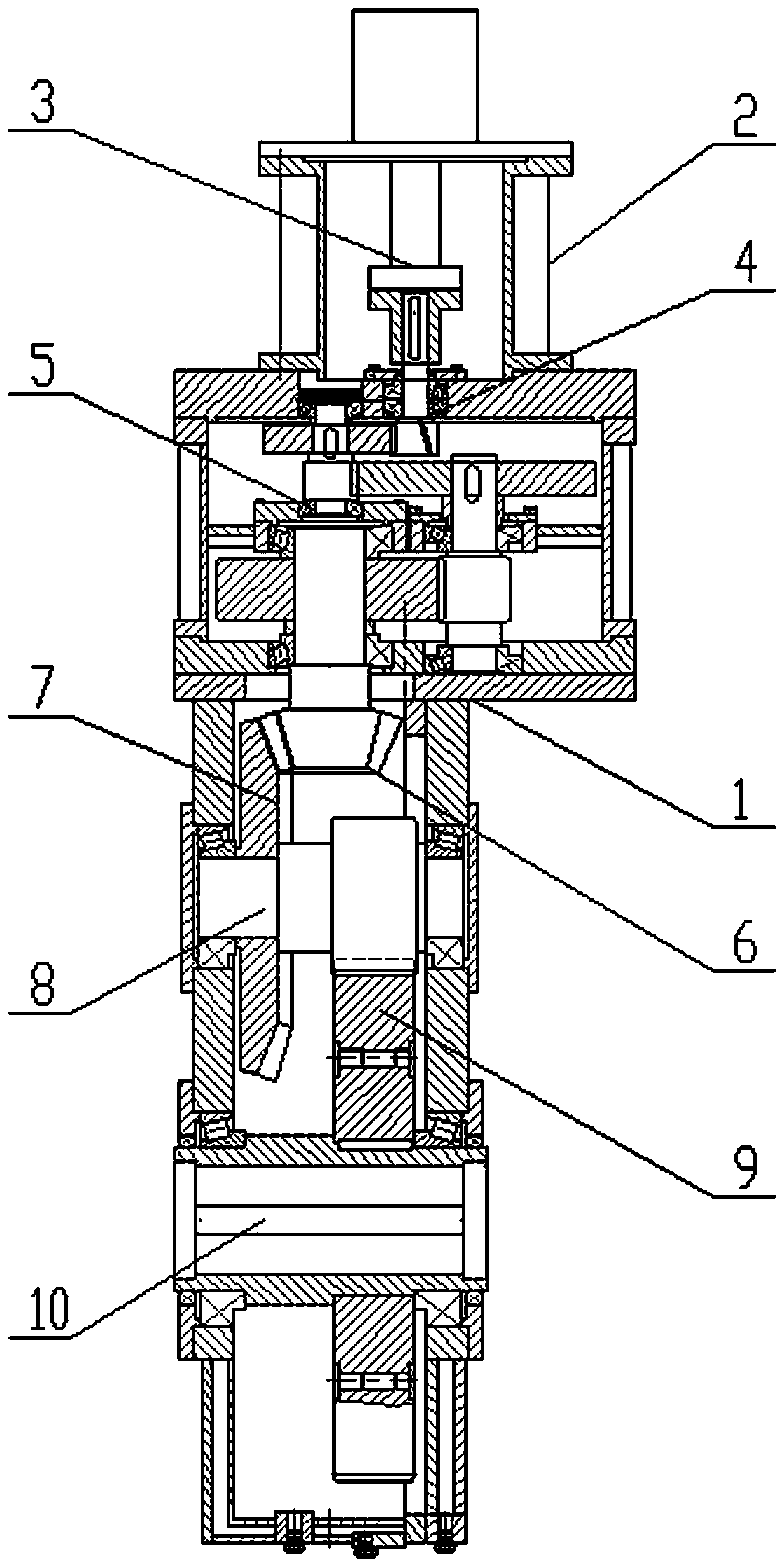
[0010] figure 1 Shown: a high-torque reducer for tension leveling machine includes box body 1, motor flange 2, coupling 3, input gear shaft 4, two-stage cylindrical gear transmission group 5, small bevel gear 6, final stage large cone Gear 7, final stage gear shaft 8, output bull gear 9, output hollow shaft 10. The two-stage cylindrical gear transmission group, the final bevel gear, the final gear shaft, the output large gear and the output hollow shaft are arranged in the box body 1, the motor flange 2 is arranged on one side of the box body, and the input gear shaft is installed in the motor flange. Extending into the box, the input gear shaft 4 outside the box is connected to the coupling 3, the input gear shaft 4 in the box is connected to the two-stage cylindrical gear transmission group 5 through transmission, and the second stage of the two-stage cylindrical gear transmission ...


PUM


Abstract

The invention relates to a large torque reduction box for a withdrawal and straightening machine. One or more stages of cylinder gear transmission sets, a tail stage taper gear, a tail stage gear shaft, an output large gear and an output hollow shaft are arranged in a box, a motor flange is arranged on one side of the box, an input gear shaft extends into the box from the motor flange, the part, outside the box, of the input gear shaft is connected with a coupler, a tooth part of the part, inside the box, of the input gear shaft is in transmission connection with the one or more stages of cylinder gear transmission sets, a cylinder gear shaft of the last stage of cylinder gear transmission set in the one or more stages of cylinder gear transmission sets is provided with a small taper gear,the small taper gear is meshed with a tail stage large taper gear connected to the tail stage gear shaft in a sleeving manner, and the tooth part of the tail stage taper gear is meshed with an outputlarge gear connected to the output hollow shaft in a sleeving manner. The large torque reduction box is simple in structure and capable of effectively giving consideration to the high speed ratio andthe large torque.

Description

technical field [0001] The invention relates to a speed reducer, in particular to a high-torque speed reducer for a tension straightening machine. Background technique [0002] The reducer used on the metallurgical continuous casting tension leveling machine is generally composed of a box body, a box cover, a flange, an input shaft, a hollow shaft and a gear transmission mechanism. The traditional cylindrical gear transmission mechanism cannot take into account the high speed ratio and high torque requirements of its use. However, the existing bevel gear set input can meet the speed ratio requirements, but the final torque is relatively small, and cannot meet the increasingly high continuous casting requirements. Contents of the invention [0003] The invention provides a high-torque speed reducer for a tension leveling machine with a simple structure and can effectively meet the requirements of a large speed ratio and a large torque. [0004] The technical solution adopt...

Claims


Application Information

Patent Timeline
Patent Type & Authority Applications(China)
IPC IPC(8): F16H1/22B22D11/12
CPCF16H1/222B22D11/1226
Inventor 赵诗韵刘燕刘涵波张介禄
Owner JIANGSU TAILONG MACHINERY GRP CO CO LTD
Why Eureka
Try Eureka