Check patentability & draft patents in minutes with Patsnap Eureka AI!

Optical biomedical sensor module and manufacturing method thereof

A manufacturing method and sensor technology, applied in optical sensors, photometry, optical radiation measurement, etc., can solve problems such as the difficulty of further miniaturization of wearable devices, and achieve the effect of reducing light loss

Active Publication Date: 2019-11-29
LITE ON OPTO TECH (CHANGZHOU) CO LTD +1
View PDF5 Cites 0 Cited by
  • Summary
  • Abstract
  • Description
  • Claims
  • Application Information

AI Technical Summary

Problems solved by technology

[0004] However, as digital electronic products such as wearable devices continue to become thinner and smaller, the existing optical biomedical sensor module 1 has both the light-receiving element 12 and the light-emitting element 13 arranged on the printed circuit board 11 On the installation surface 111 of the same level, it is difficult to further miniaturize the structure of the existing optical biomedical sensor module 1 when it is applied to a wearable device

Method used


Image

  • Optical biomedical sensor module and manufacturing method thereof
  • Optical biomedical sensor module and manufacturing method thereof
  • Optical biomedical sensor module and manufacturing method thereof

Examples


Embodiment Construction

[0042] The present invention will be described in detail below in conjunction with the accompanying drawings and embodiments.

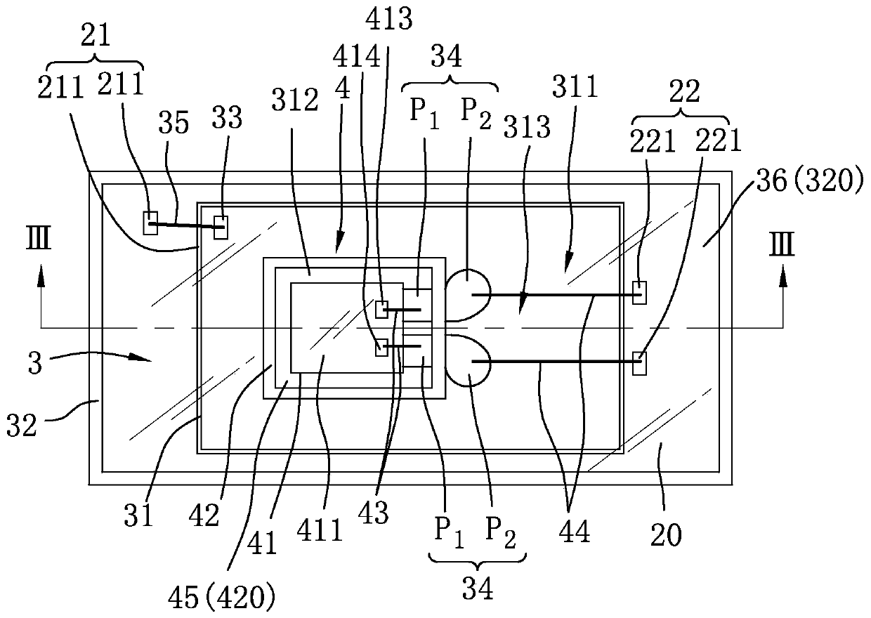
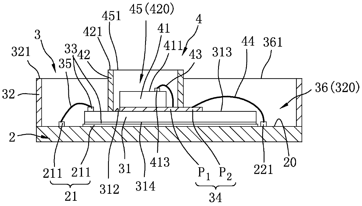
[0043] refer to figure 2 and image 3 , a first embodiment of the optical biomedical sensor module of the present invention. The optical biomedical sensor module includes a circuit board 2 , a light receiving unit 3 stacked on the circuit board 2 , and a light emitting unit 4 stacked on the light receiving unit 3 .

[0044] Specifically, the circuit board 2 includes a setting surface 20 , and a first circuit 21 and a second circuit 22 respectively disposed on the setting surface 20 and electrically connected to the light receiving unit 3 and the light emitting unit 4 .

[0045] The light-receiving unit 3 is stacked on the installation surface 20 of the circuit board 2, and includes a light-receiving element 31, a light-receiving element light-blocking wall 32, a pair of first electrode pads 33, and a pair of second electrodes Pad 34. The light re...


PUM


Abstract

An optical biomedical sensor module includes a circuit board, a light receiving unit stacked on the circuit board, and a light emitting unit stacked on the light receiving unit. There is a corresponding light blocking structure between the light-emitting unit and the light-receiving unit, so as to prevent the light emitted by the light-emitting unit from directly hitting the light-receiving unit. The relationship between the light-emitting unit and the light-receiving unit is stacked up and down, which can not only achieve the effect of reducing the size of the components to make the volume of the wearable device smaller, but also make the light-emitting unit closer to a user, so that The optical path of an incident light radiated from the light-emitting element to the user's skin is shortened, thereby reducing light loss and achieving power saving effect. The present invention also provides a manufacturing method of the aforementioned optical biomedical sensor module.

Description

technical field [0001] The invention relates to a sensor module, in particular to an optical biomedical sensor module and a manufacturing method thereof. Background technique [0002] With the concept of modern people focusing on health management and the rise of wearable devices, sensors that measure human heart rate or blood oxygen and other related health information by detecting photoplethysmography (PPG) have been gradually applied to many wearable devices middle. [0003] refer to figure 1 , an existing optical biomedical sensor module 1, which includes a printed circuit board (PCB) 11, a light receiving element 12 and a light emitting element 13 arranged on the same level of the printed circuit board 11 On the installation surface 111 , there is a light blocking wall 14 surrounding the light receiving element 12 and the light emitting element 13 . In the optical biomedical sensor module 1 , the light receiving element 12 is a sensor using the aforementioned photopl...

Claims


Application Information

Patent Timeline
Patent Type & Authority Patents(China)
IPC IPC(8): H01L25/16A61B5/00
CPCA61B5/0059H01L25/167A61B5/6801H01L2224/05554H01L2224/48091H01L2224/49175H01L2224/73265A61B5/14552G01J1/0214H01L31/167H01L33/52H01L33/62H01L2933/005H01L2933/0066H01L2924/00014A61B5/0205A61B5/02433A61B5/0816A61B2562/0238G01J1/0209G01J1/08H01L25/165H01L31/02005
Inventor 陈泓瑞何璨佑周孟松
Owner LITE ON OPTO TECH (CHANGZHOU) CO LTD
Features
  • R&D
  • Intellectual Property
  • Life Sciences
  • Materials
  • Tech Scout
  • Unparalleled Data Quality
  • Higher Quality Content
  • 60% Fewer Hallucinations
Learn More