
Ultra-wideband lens antenna based on periodic semi-high pins

A lens antenna and periodic technology, applied in the direction of antennas, electrical components, etc., can solve the problems of narrow antenna bandwidth, difficult processing, dielectric loss, etc., and achieve the effect of high antenna efficiency, high processing precision, and easy processing

Inactive Publication Date: 2018-05-25
XIDIAN UNIV
View PDF3 Cites 12 Cited by
  • Summary
  • Abstract
  • Description
  • Claims
  • Application Information

AI Technical Summary

Problems solved by technology

[0003] To sum up, the problems existing in the existing technology are: the existing dielectric lens antenna has dielectric loss, which reduces the efficiency of the antenna, and the processing is difficult; the lens antenna made of metamaterials cannot be used because its unit structure is sensitive to frequency. Stable refractive index over a wide frequency band, the antenna bandwidth is narrow, and when the required refractive index range is high, this bandwidth limitation is more serious

Method used


Image

  • Ultra-wideband lens antenna based on periodic semi-high pins
  • Ultra-wideband lens antenna based on periodic semi-high pins
  • Ultra-wideband lens antenna based on periodic semi-high pins

Examples


Embodiment Construction

[0023] In order to make the object, technical solution and advantages of the present invention more clear, the present invention will be further described in detail below in conjunction with the examples. It should be understood that the specific embodiments described here are only used to explain the present invention, not to limit the present invention.

[0024] The application principle of the present invention will be described in detail below in conjunction with the accompanying drawings.

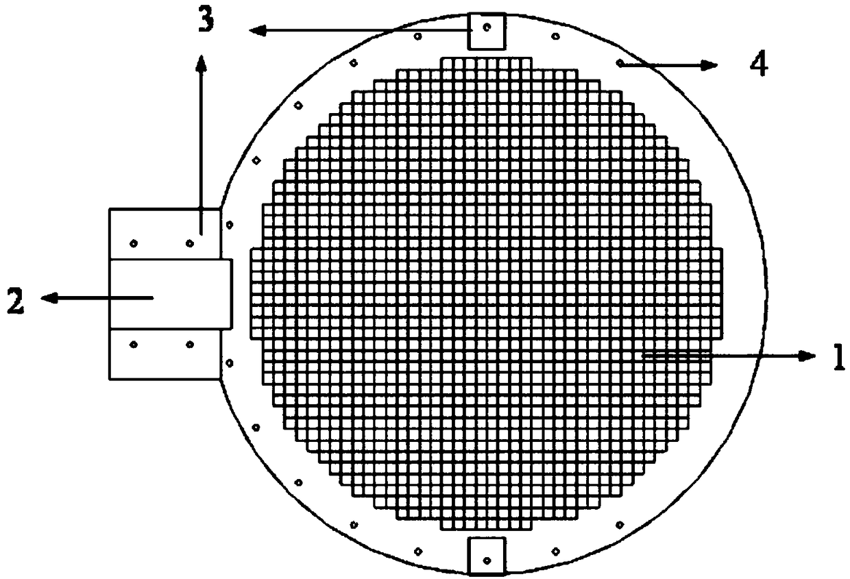
[0025] Such as figure 1 As shown, the ultra-wideband lens antenna based on periodic half-height pins provided by the embodiment of the present invention includes: a lens body 1 , a feed source 2 , a support block 3 , and a screw 4 .

[0026] The feed 2 is a rectangular waveguide located on one side of the lens; the support block 3 is metal, located on both sides of the lens body 1 in the vertical direction of the lens radiation, and the screws 4 are installed on both sides of the feed...


PUM


Abstract

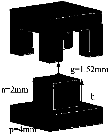
The invention belongs to the technical field of lens antennas, and discloses an ultra-wideband lens antenna based on periodic semi-height pins. The lens antenna comprises a lens body, a feed source, supporting blocks and screws; the lens body is composed of two layers of metal plates with the periodic translation symmetric half-height pins, the sides, provided with the pins, on the metal plates are arranged oppositely, and an air gap is reserved between the sides; the pins on the upper metal plate horizontally move by half of a unit period in the periodical distribution direction relative to the pins on the lower metal plate; the feed source is a rectangular waveguide and is located on one side of the lens body, and the height of the narrow edge at the tail end of the waveguide is the sumof the height of the edge pin of the lens body and the height of the air gap; the supporting blocks are located at the edges of the two sides of the lens body in the direction perpendicular to the radiation direction of the lens body; the screws are installed on the two sides of the feed source and the non-radiation edge of the lens body. The lens antenna can achieve high gain in an ultra-wide frequency band range, is easy to process and low in cost, and can be applied to the field of wireless communication such as satellite communication.

Description

technical field [0001] The invention belongs to the technical field of lens antennas, in particular to an ultra-wideband lens antenna based on periodic half-height pins. Background technique [0002] The antenna is an important device for receiving and transmitting electromagnetic waves. In order to achieve long-distance transmission, the antenna is usually required to have a high gain. Because of its high gain, the lens antenna is widely used in the communication field. At present, most lens antennas use dielectrics. For Lunberg lenses, the permittivity is gradually changing. The permittivity of the outermost surface is 1, and the permittivity of the center is 2. The permittivity changes from the center to the edge. Satisfy ε r (r)=2-(r / R) 2 (0≤r≤R), where R is the radius of the lens antenna, and r is the distance from any point on the lens to the center of the circle. However, in reality, it is difficult for the dielectric substrate to satisfy the continuity of its diel...

Claims


Application Information

Patent Timeline
IPC IPC(8): H01Q19/06H01Q15/08
CPCH01Q15/08H01Q19/06
Inventor 樊芳芳张稼宸伍金霄鄢泽洪张天龄
Owner XIDIAN UNIV
Learn More