Double-termination battery floating charge device

A floating charging and equipment technology, applied in the field of electronics, can solve the problems of not being scientific enough, not realizing charging, etc.

Inactive Publication Date: 2018-05-25
CHONGQING NINGLAI SCI & TRADE
View PDF0 Cites 0 Cited by
  • Summary
  • Abstract
  • Description
  • Claims
  • Application Information

AI Technical Summary

Problems solved by technology

[0004] The reason why the most scientific charging has not been realized is that the current products either only use DC to charge the battery, but do not use a better method, such as constant current charging; or although they can be charged with a constant current source, However, there are still some conveniences in use, or it is not scientific enough on the line, etc., so it should be enriched and developed

Method used


Image

  • Double-termination battery floating charge device
  • Double-termination battery floating charge device
  • Double-termination battery floating charge device

Examples


Embodiment Construction

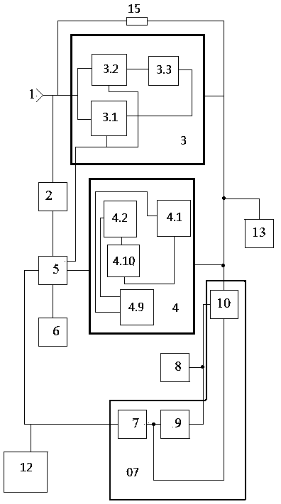
[0128] figure 1 , 2 , 3 examples of an implementation of the workpiece example.

[0129] 1. Select components: 1. The charging switching circuit is composed of two or three diodes connected in series.

[0130] 2. The counter is an integrated circuit CD4060 composed of an oscillator and a binary serial counter.

[0131] 3. The counting adjustment resistor is composed of a fixed resistor and an adjustable resistor in series.

[0132] 4. All inverters except the selected inverter adopt Schmitt NOT gate, and the selected inverter adopts NPN triode.

[0133] 5. Both the selection switch and the cut-off switch are lock-type key switches.

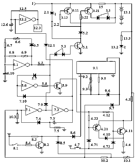
[0134] 2. Make the circuit control board, welding components: connect figure 2 Make the circuit control board according to the schematic diagram, connect figure 2 Schematic of soldered components.

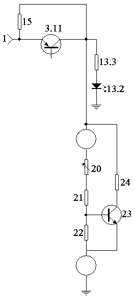
[0135] 3. Power-on inspection and debugging.

[0136] like image 3 A dummy load is shown soldered in place of the battery to be charged.

...


PUM


Abstract

The invention discloses a double-termination battery floating charge device, and belongs to the technical field of electronics. The floating charge device is composed of a floating charge unit, a discharging unit, a sound control unit, an interface unit, a pulse unit, a selection unit, a load unit, a process indicating unit, a double-termination unit, and a trickle resistor, wherein the floating charge unit, the discharging unit and the pulse unit are under the control of the interface unit, thus forming a pulse charging form that allows charging and discharging and has charging time longer than discharging time. The device includes two termination approaches, one is termination after the battery is charged and the other is termination after the timing runs up, and the two approaches are switched by the selection unit. The floating charge device is flexible and convenient. After the termination, the trickle resistor supplies required trickle current to a to-be-charged battery. In the process of charging, the process indicating unit transmits a light that flickers and is bright. Once charging is terminated, the process indicating unit flashes a long and bright light, and the sound control unit transmits a voice alert to a user. According to the embodiments of the invention, the device can charge the battery in a scientific manner and achieves maximum charging, greatly increasesthe service life of the to-be-charged battery and reduces disability rate.

Description

technical field [0001] It belongs to the field of electronic technology. Background technique [0002] Our company applied for a series of security products some time ago, and this product must have a backup battery, otherwise, when there is no mains power, the security function will become a fake, and when there is no mains power, it may be the peak of security accidents when. So a backup battery is required. And the performance of the backup battery is directly related to the overall performance. [0003] But the backup battery must be charged and maintained, and the scientific maintenance of the backup battery is directly related to the life and capacity of the backup battery. Some sources believe that batteries are often not worn out, but damaged due to improper charging. Batteries in security equipment are special-purpose batteries, which have special requirements for volume and capacity, and are more demanding than general products. [0004] The reason why the mos...

Claims


Application Information

Patent Timeline
Patent Type & Authority Applications(China)
IPC IPC(8): H02J7/00
CPCH02J7/00H02J7/0047H02J7/00711Y02E60/10
Inventor 不公告发明人
Owner CHONGQING NINGLAI SCI & TRADE
Why Eureka
Try Eureka