
Spray drying equipment for pharmaceutical factories

A technology for drying equipment and pharmaceutical factories, applied in the direction of spray evaporation, evaporator adjustment/control, evaporator accessories, etc. It can solve the problems of air pollution, drug waste, and inability to dry materials, so as to avoid environmental pollution and reduce drug waste. , the effect of reducing labor intensity

Inactive Publication Date: 2018-05-29
蚌埠精工制药机械有限公司
View PDF0 Cites 0 Cited by
  • Summary
  • Abstract
  • Description
  • Claims
  • Application Information

AI Technical Summary

Problems solved by technology

[0002] The working principle of the spray drying equipment is to disperse the raw material liquid into extremely small mist droplets with an atomizer, and use hot air to directly contact the mist droplets, and obtain a drying process of powdery and granular products through heat exchange and dehydration. Raw material liquid It can be a solution, emulsion or suspension, or a melt or a paste. The dry product can be made into powder, granule, hollow sphere or pellet according to needs, and the current drying equipment is not very good. Sufficiently drying the materials will greatly affect the quality after production, especially for pharmaceutical drugs, the drying requirements of the drugs are more stringent, and there are also strict requirements for the air release of the drugs after drying. The final air does not completely filter the medicine, which not only easily pollutes the atmospheric environment, but also causes a lot of waste of medicine, thereby greatly increasing the production cost of medicine

Method used


Image

  • Spray drying equipment for pharmaceutical factories
  • Spray drying equipment for pharmaceutical factories

Examples


Embodiment Construction

[0017] The following will clearly and completely describe the technical solutions in the embodiments of the present invention with reference to the accompanying drawings in the embodiments of the present invention. Obviously, the described embodiments are only some, not all, embodiments of the present invention.

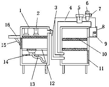
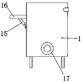
[0018] refer to Figure 1-2 , a spray drying equipment for a pharmaceutical factory, comprising a drying tank 1 and a treatment tank, the top inner wall of the drying tank 1 is fixed with two dryers 2 by bolts, and the top of the outer wall of the drying tank 1 has an air outlet, The inner wall of the air outlet is welded with a guide tube 3, and the end of the guide tube 3 away from the drying tank 1 is plugged into the processing tank. The inner wall of the drying tank 1 is provided with a support plate 13 and a partition 12, and the partition 12 is located on the support Directly above the plate 13, the four-side outer walls of the partition plate 12 and the four-...


PUM


Abstract

The invention discloses spray drying equipment for pharmaceutical factories. The equipment comprises a drying tank and a treatment tank, wherein two dryers are fixed on the inner wall of the top of the drying tank through bolts; an air outlet is formed in the top of the outer wall of one side of the drying tank; a diversion pipe is welded with the inner wall of the air outlet; the end, far from the drying tank, of the diversion pipe is spliced with the interior of the treatment tank; a supporting plate and a baffle are arranged on the inner wall of the drying tank; the baffle is positioned right above the supporting plate; the outer walls of the four sides of the baffle and the outer walls of the four sides of the supporting plate are respectively welded with the inner walls of the four sides of the drying tank; an atomizer is fixed on the outer wall of the top of the supporting plate through screws; a plastic hose is welded with the input end of the atomizer. The equipment can detectthe quality of exhausted gas in real time, effectively avoids environment pollution, performs filtering through two filtering screens, avoids discharge of medicine residues in the gas, and reduces medicine waste, provides convenience for collection of dried medicine, performs automatic drying treatment, and reduces the labor intensity of workers.

Description

technical field [0001] The invention relates to the technical field of spray drying equipment, in particular to a spray drying equipment used in a pharmaceutical factory. Background technique [0002] The working principle of the spray drying equipment is to disperse the raw material liquid into extremely small mist droplets with an atomizer, and use hot air to directly contact the mist droplets, and obtain a drying process of powdery and granular products through heat exchange and dehydration. Raw material liquid It can be a solution, emulsion or suspension, or a melt or a paste. The dry product can be made into powder, granule, hollow sphere or pellet according to needs, and the current drying equipment is not very good. Sufficiently drying the materials will greatly affect the quality after production, especially for pharmaceutical drugs, the requirements for drying the drugs are more stringent, and there are also strict requirements for the air release of the drugs after...

Claims


Application Information

Patent Timeline
IPC IPC(8): B01D1/18B01D1/30
CPCB01D1/18B01D1/0041B01D1/0082B01D1/30
Inventor 金波
Owner 蚌埠精工制药机械有限公司
Learn More