
Internal and external mixed heating type continuous carbonizing device

The technology of a carbonization device and a carbonization chamber is applied in the field of continuous carbonization devices with mixed heating inside and outside. The effect of production efficiency, reducing work intensity and reducing pollution

Inactive Publication Date: 2018-05-29
许辰光
View PDF4 Cites 0 Cited by
  • Summary
  • Abstract
  • Description
  • Claims
  • Application Information

AI Technical Summary

Problems solved by technology

The split-type carbonization furnace group must realize hot gas circulation for carbonization production through the operation of the heat pump. Once the power failure occurs, the heat pump cannot work normally, and the production can only be stopped if the heat pump fails. Long carbonization time

Method used


Image

  • Internal and external mixed heating type continuous carbonizing device
  • Internal and external mixed heating type continuous carbonizing device
  • Internal and external mixed heating type continuous carbonizing device

Examples


Embodiment 1

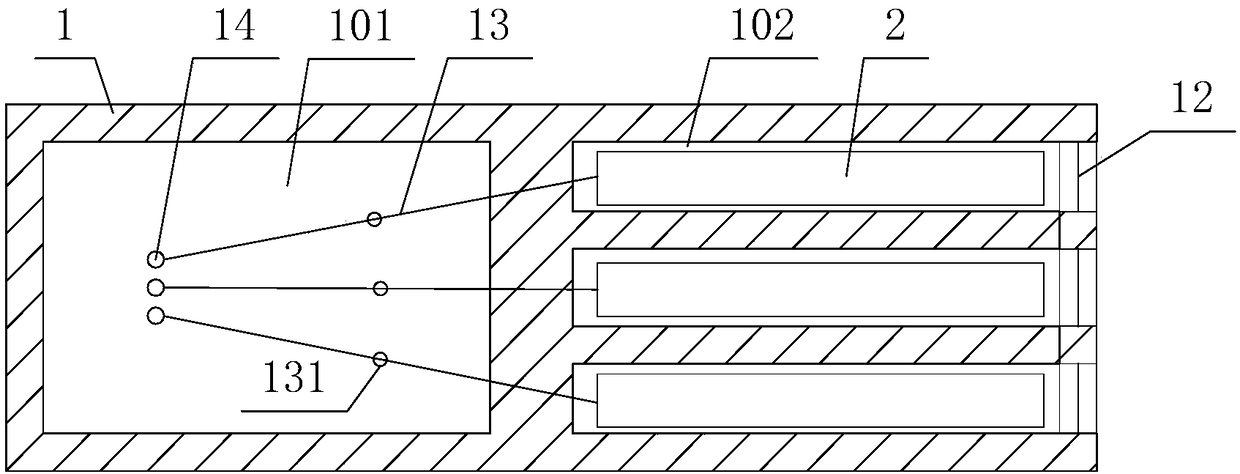
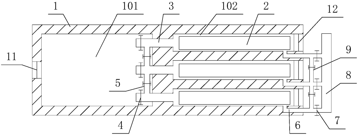
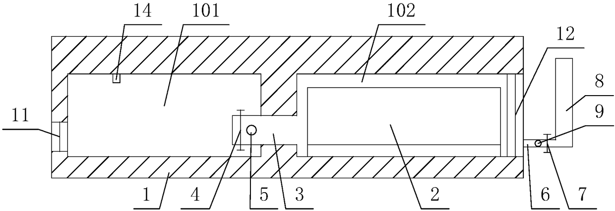
[0052] Such as Figure 1 to Figure 3 As shown, the internal and external mixed heating continuous carbonization device provided by the embodiment of the present invention includes a furnace body 1 and a material box 2 .

[0053] The furnace body 1 is provided with a combustion chamber 101 and a carbonization chamber 102 for accommodating the material box 2 .

[0054] There are at least two carbonization chambers 102 arranged side by side along the horizontal direction.

[0055] In this embodiment, three carbonization chambers 102 are taken as an example for illustration.

[0056] Such as figure 2 and image 3 As shown, the three carbonization chambers 102 are all arranged adjacent to the combustion chamber 101 . In this embodiment, all the carbonization chambers 102 are located on the same side of the combustion chamber 101 in the horizontal direction. A furnace door 11 is provided on a side of the combustion chamber 101 away from the carbonization chamber 102 .

[0057...

Embodiment 2

[0097] The difference between this embodiment 2 and embodiment 1 is: in this embodiment, if Figure 9 As shown, all the carbonization chambers 102 are located directly above the combustion chamber 101 .

[0098] In this embodiment, four carbonization chambers 102 are provided. The bottom of one end of the four carbonization chambers 102 communicates with the combustion chamber 101 through the heat conduction pipe 3 , and a flue 6 is respectively arranged at the lower side of the other end of the four carbonization chambers 102 .


PUM


Abstract

The invention provides an internal and external mixed heating type continuous carbonizing device. The device comprises a furnace and material boxes, wherein a combustion chamber and at least two carbonizing chambers close to the combustion chamber are arranged in the furnace, each carbonizing chamber is communicated with the combustion chamber through a heat conducting pipeline provided with a fireproof valve, each carbonizing chamber is provided with a flue, and a material door is arranged on the furnace; one material box is arranged in each carbonizing chamber, a support is arranged at the bottom of each material box, so that a hot air channel is formed between the bottom of each material box and the corresponding carbonizing chamber, two ends of each hot air channel are communicated with the corresponding heat conducting pipeline and the corresponding flue; each material box is provided with an ignition structure and an air pipe, the inside of each material box is communicated withthe atmosphere through the corresponding air pipe, and each material box is open at the top and is detachably connected with a box cover in a sealed manner; gas pipelines are also arranged at the topof the combustion chamber, gas outlet ends of all the gas pipelines are communicated with the inside of the combustion chamber, and gas inlet ends of all the gas pipelines are communicated with the material boxes in the carbonizing chambers in a one-to-one correspondence manner. The device has the characteristics that the carbonization time is short and the production process is environmentally friendly.

Description

technical field [0001] The invention relates to the technical field of carbonization, in particular to a continuous carbonization device with internal and external mixed heating. Background technique [0002] The environmental pollution problem of the charcoal industry is in huge contrast with people's increasing consumption requirements. The demand for high-quality charcoal is strong, and the green production with low energy consumption and low carbon is deeply rooted in the hearts of the people. Existing internal heat type carbonization furnace discharges a large amount of smoke and dust outside, causing great pollution. [0003] There is a split-type carbonization furnace group, which consists of a combustion furnace, a heat pump and a carbonization furnace. The combustion furnace, heat pump and carbonization furnace are connected in sequence through pipelines. More than three parallel access processes. The split-type carbonization furnace group must realize hot gas ci...

Claims


Application Information

Patent Timeline
IPC IPC(8): C10B53/00C10B51/00
CPCC10B53/00C10B51/00
Inventor 许辰光
Owner 许辰光
Learn More