
Fluidized bed gas distributor, fluidized bed reactor and gasification method

A technology of gas distributor and gas distribution plate, which is applied in the field of coal gasification, can solve the problems of large dead zone area, uneven contact, local high temperature, etc., and achieve the effects of uniform heat distribution, improved uniformity, and enhanced fluidization effect

Inactive Publication Date: 2018-05-29
ENN SCI & TECH DEV
View PDF2 Cites 1 Cited by
  • Summary
  • Abstract
  • Description
  • Claims
  • Application Information

AI Technical Summary

Problems solved by technology

[0005] However, for the medium and high pressure coal gasification process, especially the coal catalytic gasification process, the solid phase bed in the fluidized bed reactor is relatively high, and its operating pressure is high, and the gas compression is serious, while the existing gas distributor is Located at the bottom of the fluidized bed reactor, the gasification agent enters the reaction chamber through the gas distributor and only contacts the bed in a small part of the bottom area, and the gasification agent has less contact with the bed in the upper area. This leads to uneven contact between the gasification agent and the entire bed, resulting in uneven fluidization of the bed, and a large dead area for the gasification agent to flow in the upper bed, which is not conducive to the gasification agent and the bed. The reaction of the bed; the poor fluidization of the bed and the large dead area of ​​the gasification agent in the upper part of the bed will easily lead to uneven distribution of the heat released by the combustion of oxygen in the gasification agent, resulting in local high temperature, resulting in gas distributors Particle sintering and slagging in the surrounding bed area will have a negative impact on the stability of the fluidized bed reactor, and eventually cause the fluidized bed reactor to fail to operate stably and be forced to stop

Method used


Image

  • Fluidized bed gas distributor, fluidized bed reactor and gasification method
  • Fluidized bed gas distributor, fluidized bed reactor and gasification method
  • Fluidized bed gas distributor, fluidized bed reactor and gasification method

Examples


Embodiment 1

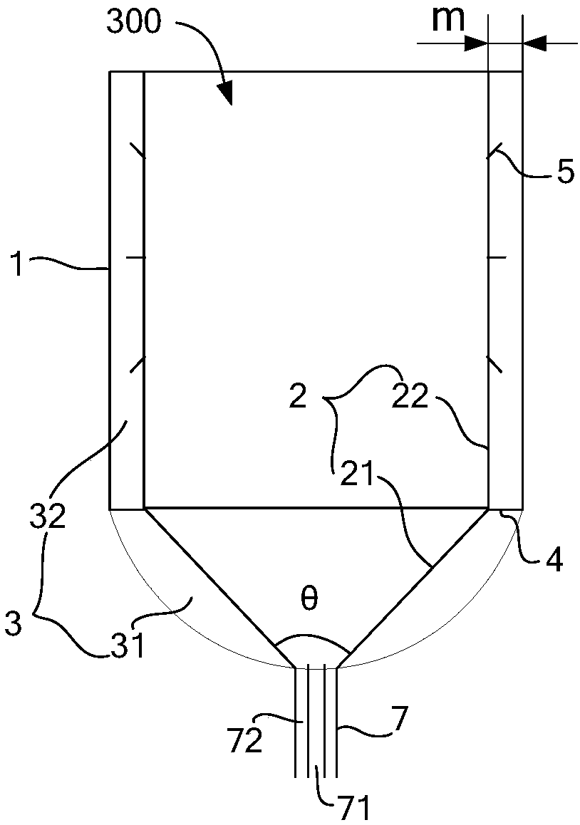
[0026] Such as image 3 As shown, the embodiment of the present invention provides a gas distributor for a fluidized bed, which includes a cylindrical first shell 1 with an open upper end and a sealed lower end. The first shell 1 is provided with a gas distribution plate 2 for gas distribution. A gas chamber 3 is formed between the plate 2 and the first housing 1. The gas chamber 3 includes a first gas chamber 31 and a second gas chamber 32 isolated from each other. The gas distribution plate 2 includes a first gas distribution plate 21 and a second gas distribution plate 21. Distribution plate 22, the second gas distribution plate 22 is located above the first gas distribution plate 21, the second gas distribution plate 22 is cylindrical and vertically arranged, the first gas distribution plate 21 is connected to the lower end of the second gas distribution plate 22 , the first gas distribution plate 21 corresponds to the first gas chamber 31 , and the second gas distribution...

Embodiment 2

[0059] Such as figure 1 As shown, the embodiment of the present invention provides a fluidized bed reactor, including a cylindrical second shell 200 with a sealed upper end and an open lower end and the fluidized bed gas distributor 100 described in Embodiment 1. The lower end of the second housing 200 is sealingly connected with the upper end of the first housing 1 of the fluidized bed gas distributor 100, so that a reaction chamber is formed between the second housing 200 and the gas distribution plate 2 of the fluidized bed gas distributor 100 Room 300.

[0060] Wherein, the first shell 1 and the second shell 200 can be integrally formed (for example figure 1 shown), the lower end of the second housing 200 and the upper end of the first housing 1 may also be sealed and connected through a connection structure, which is not specifically limited here.

[0061] Since the fluidized bed gas distributor 100 included in the fluidized bed reactor provided by the embodiment of the...

Embodiment 3

[0066] Such as Figure 7 As shown, the embodiment of the present invention provides a gasification method of a fluidized bed reactor as described in Example 2, comprising the following steps:

[0067] S1. Send carbonaceous material (such as coal) with a certain amount of catalyst loading into the reaction chamber 300, and at the same time send the gasification agent into the first gas chamber 31 and the second gas chamber 32 respectively, and send it into The gasification agent in the first gas chamber 31 enters the reaction chamber 300 through the first gas distribution plate 21, and the gasification agent sent into the second gas chamber 32 enters the reaction chamber through the second gas distribution plate 22 chamber 300, so that the carbonaceous material and the gasifying agent undergo a gasification reaction;

[0068] Among them, such as figure 1 As shown, the carbonaceous material can be fed into the reaction chamber 300 through the feed port 204 provided on the seco...


PUM

PropertyMeasurementUnit
The inside diameter ofaaaaaaaaaa

Abstract

The invention discloses a fluidized bed gas distributor, a fluidized bed reactor and a gasification method, relates to the technical field of coal gasification and can increase the fluidization effectof a bed layer and reduce a flow dead zone of a gasification agent on an upper bed layer. The fluidized bed gas distributor comprises a cylindrical first housing with an opened upper end and a sealedlower end; a gas distribution plate is arranged in the first housing, a gas chamber comprises a first gas chamber and a second gas chamber which are mutually separated from each other and is enclosedbetween the gas distribution plate and the first housing, the gas distribution plate comprises a first gas distribution plate and a second gas distribution plate, the second gas distribution plate ispositioned above the first gas distribution plate, is cylindrical and is vertically arranged, the first gas distribution plate is connected with the lower end of the second gas distribution plate, the first gas distribution plate corresponds to the first gas chamber, and the second gas distribution plate corresponds to the second gas chamber. The fluidized bed gas distributor, the fluidized bed reactor and the gasification method disclosed by the invention can be used for the generation of coal gas.

Description

technical field [0001] The invention relates to the technical field of coal gasification, in particular to a fluidized bed gas distributor, a fluidized bed reactor and a gasification method thereof. Background technique [0002] Coal catalytic gasification technology is an important way of clean and efficient utilization of coal, and it is one of the most efficient gasification technologies for coal-to-natural gas. Coal catalytic gasification is usually carried out in a fluidized bed reactor (such as a common fluidized bed gasifier), in which the raw coal is kept under the action of a bottom-up gasification agent. Continuous boiling and suspension state movement, rapid mixing and heat exchange, the coal gas generated by the reaction of raw coal and gasification agent is discharged from the exhaust pipeline at the top of the fluidized bed reactor, and the slag generated by the reaction is discharged from the fluidized bed reactor. It is discharged from the slag discharge lin...

Claims


Application Information

Patent Timeline
IPC IPC(8): C10J3/54C10J3/56
CPCC10J3/54C10J3/56C10J2200/15C10J2300/093C10J2300/0959C10J2300/0976
Inventor 刘雷毛燕东李克忠
Owner ENN SCI & TECH DEV
Learn More