A flow control method for an accumulator of a hub motor hydraulic drive system

A hub motor and drive system technology, applied in fluid pressure actuation system components, fluid pressure actuation devices, mechanical equipment, etc., can solve problems such as insignificant boosting effect, energy waste, and large vehicle curb weight

Inactive Publication Date: 2019-07-26
JILIN UNIV
View PDF7 Cites 0 Cited by
  • Summary
  • Abstract
  • Description
  • Claims
  • Application Information

AI Technical Summary

Problems solved by technology

However, due to factors such as large accumulator weight, high cost, difficult vehicle layout, and large vehicle curb weight, it is rarely used in real vehicles.
In addition, the power assist control of the accumulator used in the actual vehicle is relatively extensive, only opening the drain valve of the accumulator to drive the front wheels for power assist, resulting in the output torque of the front wheels being greater than the required torque, causing the drive wheels to slip or the front wheels to The speed is too fast and the rear wheel is dragged to rotate, resulting in insignificant power assist effect and waste of energy

Method used


Image

  • A flow control method for an accumulator of a hub motor hydraulic drive system
  • A flow control method for an accumulator of a hub motor hydraulic drive system
  • A flow control method for an accumulator of a hub motor hydraulic drive system

Examples


Embodiment Construction

[0089] The present invention will be further described below in conjunction with accompanying drawing:

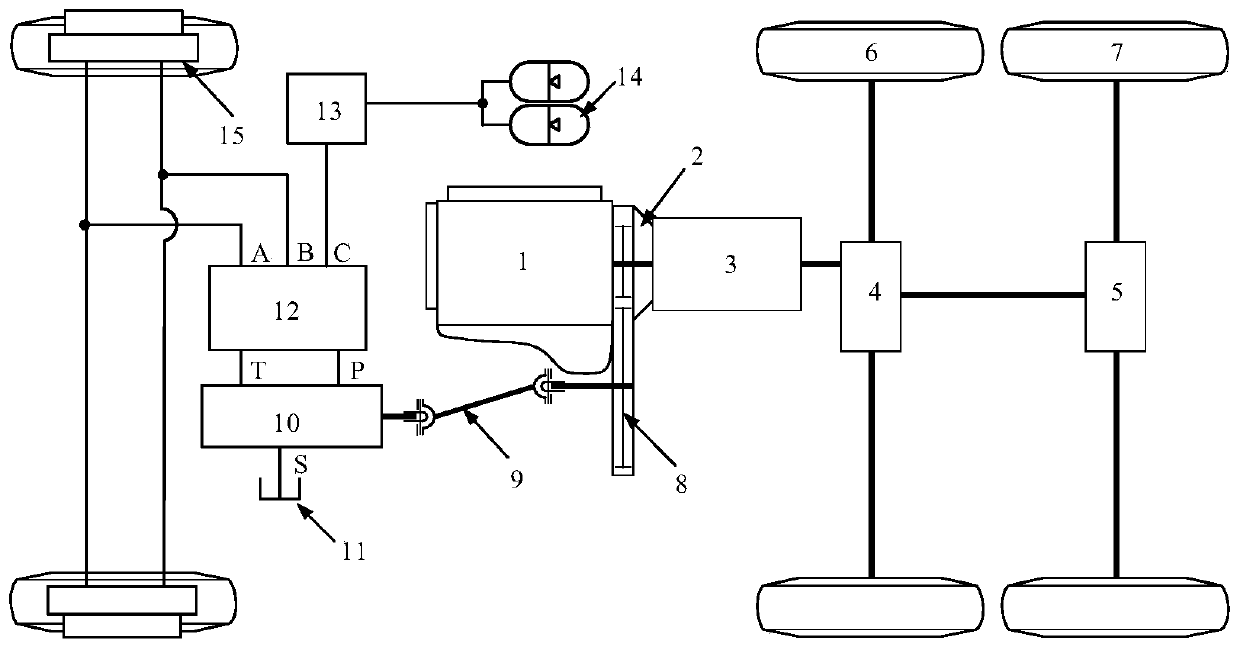
[0090] A hub motor hydraulic drive system accumulator flow control method, based on a hub motor hydraulic drive system, such as figure 1 As shown, including 1. Engine, 2. Clutch, 3. Transmission, 4. Center axle drive axle, 5. Rear axle drive axle, 6. Center axle drive wheel, 7. Rear axle drive wheel, 8. Power take-off, 9. Universal joint, 10. Hydraulic pump assembly, 11. Oil tank, 12. Hydraulic control valve group, 13. Accumulator control valve group, 14. Accumulator, 15. Quantitative motor.

[0091] The output shaft of the engine 1 is mechanically connected to the input shaft of the clutch 2, the output shaft of the clutch 2 is mechanically connected to the input shaft of the transmission 3, the output shaft of the transmission 3 is mechanically connected to the center axle drive axle 4, and the center axle drive axle 4 is connected to the center axle The drive wheel 6 is...


PUM


Abstract

The invention provides an energy accumulator flow control method of a hub motor hydraulic drive system and belongs to the field of control over oil-liquid hybrid electric vehicles. The energy accumulator flow control method comprises the steps of determining the front wheel target drive torque of an automobile, determining the pressure of a quantitative motor oil inlet, namely the pressure of an energy accumulator oil outlet, based on the front wheel target drive torque, and realizing set-pressure flow control of an energy accumulator through a DA control valve. By means of the energy accumulator flow control method, the algebraic relation between the front wheel target drive torque and the energy accumulator flow is explored by researches on assisting form components of the energy accumulator; and besides, online adjustment of the flow of the energy accumulator is achieved by adopting incremental PID adjustment for feedback control over the pressure of the quantitative motor oil inlet. Under control of the control method, the output drive torque of a quantitative motor can be coincident with the front wheel target drive torque, hydraulic energy of the energy accumulator is converted to mechanical energy as much as possible on the premise that the assisting effect of the energy accumulator is ensured, and the economical efficiency of the automobile is improved.

Description

technical field [0001] The invention relates to a flow control method for an accumulator of a hub motor hydraulic drive system, which belongs to the control field of oil-hydraulic hybrid vehicles. Background technique [0002] In recent years, with the rapid development of the automobile industry, a major breakthrough has been made in the application of secondary regulation hydrostatic transmission technology in traditional vehicles. This technology has gradually attracted great attention from domestic and foreign research institutions and automobile manufacturers. In China, research on the application of hydraulic technology in automobiles is mainly concentrated in colleges and universities, and related hydraulic drive technology is mostly used in energy-saving and environmentally friendly oil-hydraulic power coupling systems, including parallel and hybrid hydraulic drive hybrid systems, etc. Hydraulic braking technology The application is also mostly limited to the researc...

Claims


Application Information

Patent Timeline
Patent Type & Authority Patents(China)
IPC IPC(8): F15B1/04F15B21/00
CPCF15B1/04F15B21/001
Inventor 曾小华刘持林李广含宋大凤李文远李立鑫崔臣
Owner JILIN UNIV
Why Eureka
Try Eureka