
Through-flow water energy navigation mark light

A beacon light and tubular technology, applied in the field of tubular water energy beacon lights, can solve the problems of affecting the power supply of the beacon light, affecting the stability of the beacon light, and the inability of the beacon light to provide the beacon light and other corresponding components, etc. Achieve the effect of improving energy utilization, realizing photovoltaic complementarity, and reducing environmental impact

Inactive Publication Date: 2018-05-29
HOHAI UNIV WENTIAN COLLEGE
View PDF10 Cites 3 Cited by
  • Summary
  • Abstract
  • Description
  • Claims
  • Application Information

AI Technical Summary

Problems solved by technology

[0006] The beacon light is an indispensable navigation facility on the river channel. Its power supply is an important component. The performance of the power supply determines the use of the beacon light. In the river channel, the flow of the river varies, which affects the stability of the beacon light on the one hand. On the other hand, it will affect the power supply of the navigation light. Aiming at the problem that the existing navigation light cannot provide energy to the navigation light and other corresponding components in the turbulent flow state of the river, the present invention provides a through-flow water energy navigation light The beacon light can not only use hydropower to generate electricity in the middle and lower reaches of rivers with low water head, but also use solar energy to generate electricity in slow-flowing waters, realize photoelectric complementarity, ensure the normal operation of the beacon light, and provide strong safety guidance for navigation

Method used


Image

  • Through-flow water energy navigation mark light
  • Through-flow water energy navigation mark light
  • Through-flow water energy navigation mark light

Examples


Embodiment 1

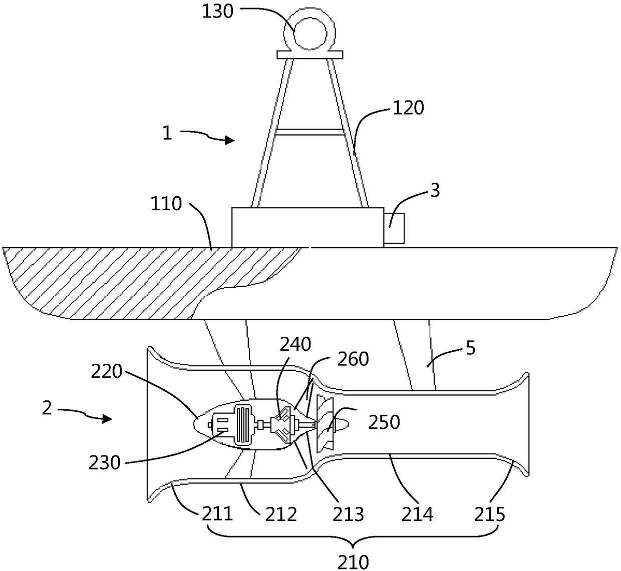
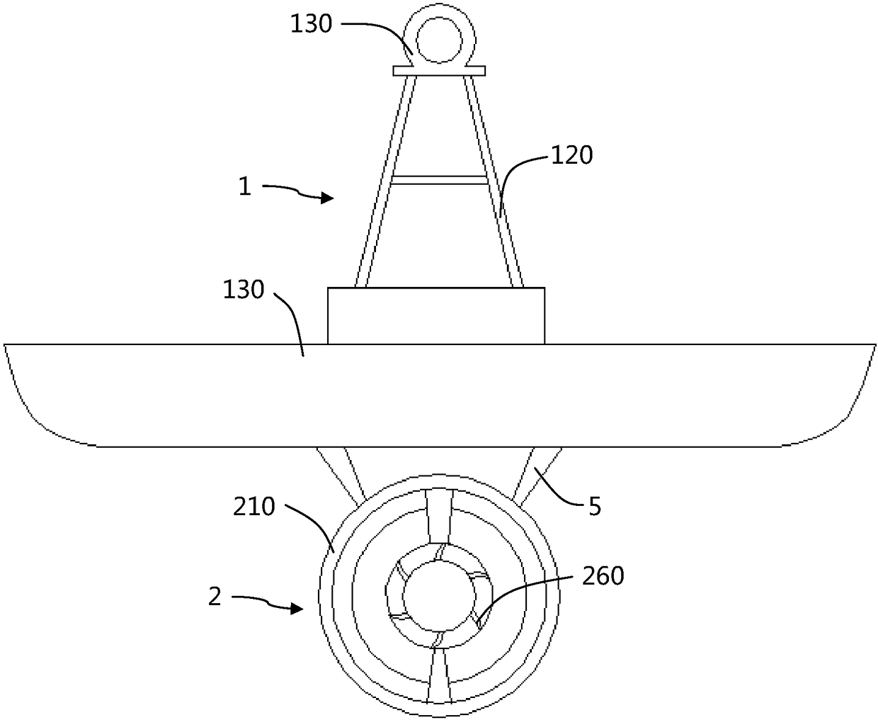
[0041] Such as Figure 1 to Figure 3 As shown, the through-flow water energy navigation light of this embodiment includes: a navigation light body 1, which includes a floating plate 110, a light stand 120 and a lamp body 130 placed on the light stand 120, and the light stand 120 is arranged on the floating plate 110, The floating plate 110 has a circular cross-section and is made of hydrophobic materials. The lamp stand 120 has a regular tetrahedron frame structure, and a surge protection circuit is arranged in the frame. The lamp body 130 is placed in the surge protection circuit, and the surge protection circuit has very strong Good anti-fluctuation, in the state of unstable voltage, so that the lamp body 130 will not be damaged by too high or too low voltage; the diversion power generation unit 2 is arranged on the lower end surface of the navigation light body 1 for receiving water energy And converted into electric energy, diversion power generation unit 2 includes divers...

Embodiment 2

[0050] From figure 1 It can also be seen that the guide power generation unit 2 also includes guide vanes 260, which are fixed on the bulb-type protective shell 220 located on the front side of the tubular turbine 250, and the guide vanes 260 are distributed in a spiral shape and enter into the The water flow in the diversion shell, because the cross section becomes smaller, its speed becomes faster, and the pressure will be too large. The guide vane 260 controls the direction of the water flow and buffers the momentum of the water head, reducing the impact on the tubular turbine, so that the continuous The flow turbine is evenly stressed and rotates more smoothly.

Embodiment 3

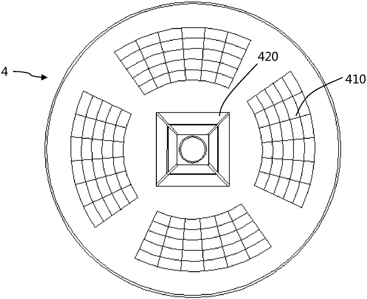
[0052] The navigation light of this embodiment is also provided with a photosensitive sensor 3 and a main board. The photosensitive sensor 3 is arranged on one side of the light stand 120, and the photosensitive sensor 3 and the lamp body 130 are both electrically connected to the main board. When the tubular turbine 250 is working, the water flow enters the tubular turbine 250 from the water inlet, drives the turbine to rotate, and then drives the generator 230 to generate electricity through the bearing. The electricity of these two parts is firstly stored by the storage battery 420 . The photosensitive sensor 3 detects the brightness of the light, and the detection brightness valve point can be adjusted through the potentiometer. When the ambient light of the module exceeds the set threshold, the relay pulls in, and the common terminal is connected to the normally open terminal. When the ambient light of the module is lower than the set threshold, the module When the thresh...


PUM


Abstract

The invention discloses a through-flow water energy navigation mark light, and belongs to the technical field of navigating devices. The through-flow water energy navigation mark light comprises a navigation mark light body and a diversion and power generation unit. The navigation mark light body comprises a floating plate, a light stand and a light body arranged on the light stand. The light stand is arranged on the floating plate. The diversion and power generation unit is arranged on the lower end surface of the navigation mark light body, and is used for receiving water energy and converting the water energy into electric energy. The diversion and power generation unit comprises a diversion housing, a bulb-type protecting shell, a power generator, a gearbox and a through-flow turbine.The power generator is arranged in the bulb-type protection shell. A main shaft of the through-flow turbine is connected with the power generator by means of the gearbox. The bulb-type protection shell is fixed in the diversion housing by virtue of a supporting plate. The through-flow turbine is taken as an energy supplying device to be combined with the navigation mark light, and is applicable tothe characteristics of high-flow low water heads in middle and lower riverways, the navigation mark light can migrate along with a main channel, enough water energy is used for power generation, andmoreover, the through-flow turbine can be used under the condition of two-way water flow, photoelectric complementary is realized, the normal operation of the navigation mark light is ensured, and a strong and safe indication is provided for sailing of steamships.

Description

technical field [0001] The invention belongs to the technical field of navigation equipment, and more specifically relates to a through-flow water energy navigation light. Background technique [0002] In order to ensure the safety of ships and crews navigating in waterways, beacon lights have become an indispensable navigation facility on rivers and waterways. The beacon lights can emit the specified light color and flash frequency (the frequency can be 0) at night to achieve the specified irradiation angle and Visible distance, guide the route of ships traveling at night. At the beginning of the manufacturing of the navigation lights, ordinary batteries are used as energy sources. The service life of the navigation lights in this way is short, and the batteries are prone to leakage. Later, with the deepening of chemical research, people use the principle of primary batteries in the navigation lights. This type of navigation light needs to be replaced with a new aluminum s...

Claims


Application Information

Patent Timeline
IPC IPC(8): F21S9/02F21S9/03F21S9/04F21V23/04F21V25/02F21W111/047
CPCF21S9/028F21S9/035F21S9/046F21V23/0464F21V25/02F21W2111/047
Inventor 邓宏远王轶群
Owner HOHAI UNIV WENTIAN COLLEGE
Learn More