Industrial calcination shaft kiln

A calcining and industrial technology, applied in vertical furnaces, waste heat treatment, furnace control devices, etc., can solve the problems of uneven temperature, sintered materials into large blocks, and short operating cycles, and achieve the effect of uniformity

Pending Publication Date: 2018-05-29
NANJING SUYE CALCIUM IND TECH
View PDF0 Cites 5 Cited by
  • Summary
  • Abstract
  • Description
  • Claims
  • Application Information

AI Technical Summary

Problems solved by technology

Since the kiln body is a straight body, and the fuel is sprayed directly onto the material after being sprayed from the burner, there is no combustion space, and it is difficult for the fuel and heat to be transmitted to the central part of the kiln, which makes the temperature uneven in the edge and middle of the same section , the temperature of the area near the burner and the area far away from the burner is not uniform, resulting in poor quality of products calcined by this vertical kiln, both raw and over-burned are serious, and the bulk density and fired state are not uniform
Especially when burning natural gas with high calorific value, due to the high local temperature, it is easy to cause the material to sinter into large pieces, burn out the refractory material, and the kiln's operating cycle is short and its service life is short
This kind of kiln is generally not suitable for burning powder fuel
[0005] In addition, due to the limitations of feeding, unloading, blasting methods, and fuel combustion, the thermal system in the kiln is unstable

Method used


Image

  • Industrial calcination shaft kiln
  • Industrial calcination shaft kiln
  • Industrial calcination shaft kiln

Examples


Embodiment 1

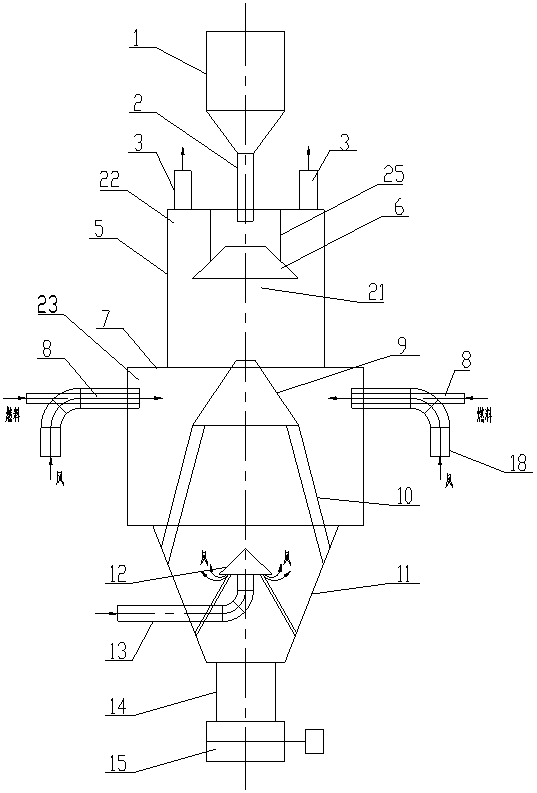
[0043] see figure 1 , 7 The industrial calcination shaft kiln shown includes a straight upper cylinder 5 , a middle cylinder 7 and a lower cylinder 11 . A feeding bin 1, a feeding pipe 2 and a distributor 6 are arranged on the upper part of the upper cylinder body 5 for filling materials into the cylinder body. The outlet end of the feeding pipe is located at the center of the top of the upper cylinder and communicates with the inside of the cylinder, and the distributor is located below the outlet of the feeding pipe. The feeding pipe 2 can be stretched relative to the upper cylinder to change the length (equivalent to the feeding pipe can move up and down relative to the upper cylinder). Distributor 6 is a conical body with a small upper part and a larger lower part. It is suspended on the top of the upper cylinder by suspension cables or suspenders 25. The suspension cables or suspenders can be adjusted to change the upper and lower positions of the distributor relative ...

Embodiment 2

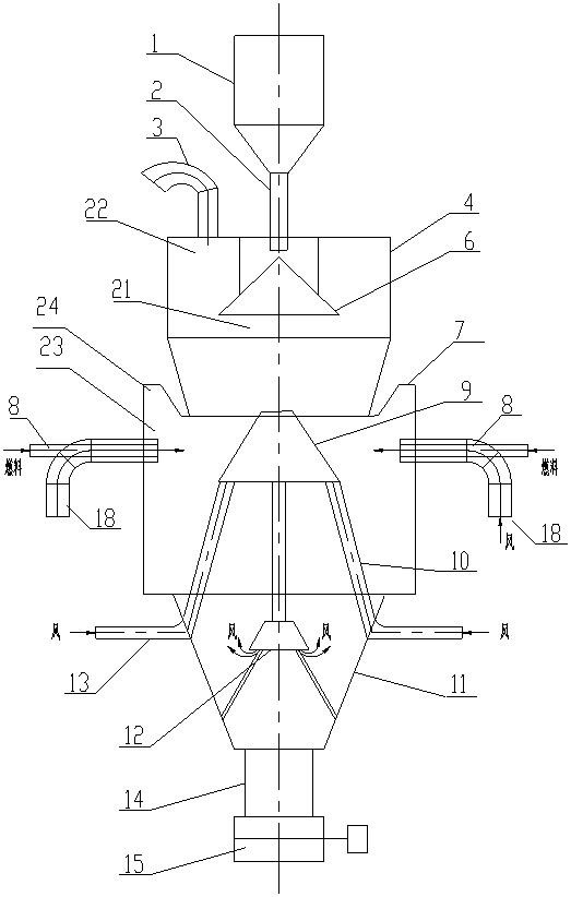
[0051] see figure 2 Shown industrial calcination shaft kiln, its difference with embodiment 1 mainly lies in:

[0052] The upper cylinder 4 in Embodiment 2 is an upper cylinder with a conical bottom with a large upper part and a smaller lower part. This is conducive to a more uniform heat exchange between the air flow and the material. This structure can be used in different said industrial calcination shaft kilns.

[0053] The upper opening of the middle cylinder body 7 in the second embodiment is shaped, and the outer circumference of the upper end thereof protrudes upwards, forming an empty area 24 communicating with the cavity 23 at the upper part of the sudden change section. This is beneficial to increase the volume of the cavity 23 . This structure can be used in different said industrial calcination shaft kilns.

[0054] The distributor 9 and the supporting legs 10 in the second embodiment are hollow structures connected internally, cooling air is passed through t...

Embodiment 3

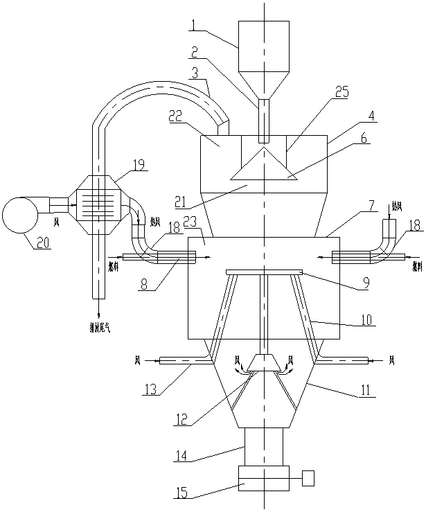
[0057] see image 3 Shown industrial calcination shaft kiln, its difference with embodiment 1 mainly lies in:

[0058] The upper cylinder body 4 in the embodiment 3 is an upper cylinder body with a conical bottom with a large top and a small bottom. This is conducive to a more uniform heat exchange between the air flow and the material. This structure can be used in different industrial calcination shaft kilns

[0059] The flue gas pipe 3 in Embodiment 3 is provided with a flue gas-air heat exchanger 19, the inlet of the combustion-supporting air supply channel 18 of the fuel combustion device is connected to the air outlet of the heat exchanger 19, and the air inlet of the heat exchanger is connected to the air outlet of the heat exchanger. Blowers 20 are connected. This structure can be used in different said industrial calcination shaft kilns.

[0060] The distributor 9 in Example 3 is a hollow plate-shaped structure, and the installation height of the distributor is lo...


PUM


Abstract

The invention discloses an industrial calcination shaft kiln. According to the industrial calcination shaft kiln, gas, liquid or power are taken as fuel, the calcination temperature is more even, theproduct quality is better, energy conservation and environmental protection are achieved, the automation degree is high, and massive or granular or ball-shaped materials can be calcined. The industrial calcination shaft kiln comprises a cylinder body, a material adding device used for adding materials to the interior of the cylinder body and an exhaust device used for exhausting tail gas are arranged on the upper portion of the cylinder body; a combustion-supporting wind device used for sending combustion-supporting wind to the interior of the cylinder body and an unloading device used for discharging the material in the cylinder body are arranged on the lower portion of the cylinder body, at least a sudden-changed section is arranged at the position, between the material adding device andthe combustion-supporting wind device, of the cylinder body, the size of the part, on the upper portion of the sudden-changed section, of an inner cavity of the cylinder body is small in the horizontal direction, the size of the part, on the lower portion of the sudden-changed section, of the inner cavity of the cylinder body is large in the horizontal direction, and when the materials flow downwards in the cylinder body, a cavity which the materials cannot reach naturally is formed on the lower portion of the sudden-changed section; and an outlet of a combustion nozzle in a fuel combustion device communicates with the cavity, and materials are sprayed out from the combustion nozzle.

Description

technical field [0001] This technology relates to a shaft kiln for calcining block, granular or spherical materials, especially a shaft kiln for calcining limestone and dolomite with gas or liquid or powder fuel, and calcining dolomite with gas or liquid fuel / High temperature shaft kiln for magnesite. Background technique [0002] Calcination shaft kiln is also called shaft kiln, shaft furnace, roasting furnace, etc. [0003] Existing shaft kilns for calcining block, granular or spherical materials of gas or liquid or powder fuel, especially shaft kilns for calcining limestone and dolomite, the calcined materials are block materials of 40-80 mm in size. High-temperature shaft kiln for calcining dolomite / magnesite with gas or liquid fuel, generally the calcined material is 20-50mm briquette material. Neither the shaft kiln nor the high-temperature shaft furnace can calcinate granular materials of 1-15 mm. The structure of this kind of shaft kiln or high temperature shaft...

Claims


Application Information

Patent Timeline
Patent Type & Authority Applications(China)
IPC IPC(8): F27B1/00F27B1/16F27B1/20F27B1/26F27B1/28F27D17/00F27D19/00C04B2/12
CPCF27B1/005C04B2/12F27B1/16F27B1/20F27B1/26F27B1/28F27D17/004F27D19/00F27D2019/004F27D2019/0056
Inventor 刘银江杭宁刘宇
Owner NANJING SUYE CALCIUM IND TECH
Why Eureka
Try Eureka