
Sensorless switch magnetic resistance motor-driven system

A technology of switched reluctance motor and drive system, applied in control system, electronic commutation motor control, electrical components, etc., can solve the problem of reducing the reliability of the drive system, increasing the cost of the switched reluctance motor drive system, and difficult to achieve high-speed motor control and other issues to achieve the effect of increasing stability

Inactive Publication Date: 2018-05-29
扬州汉龙电气有限公司
View PDF1 Cites 3 Cited by
  • Summary
  • Abstract
  • Description
  • Claims
  • Application Information

AI Technical Summary

Problems solved by technology

[0002] Switched reluctance motor is the latest generation of stepless speed regulation system developed after frequency conversion speed regulation system and brushless DC motor speed regulation system. It integrates modern microelectronic technology, digital technology, power electronics technology, infrared photoelectric technology and modern electromagnetic technology. It is a high-tech integrated optical, mechanical and electrical integration of theory, design and production technology. It has simple structure, low cost, many controllable parameters, small starting current, large starting torque, high system efficiency and good braking. Excellent features such as energy recovery performance are widely used in various electronic and mechanical fields. In recent years, they have also been widely used in the field of electric vehicles. When the number of motor phases increases, the number of sensors used in position detection devices will increase accordingly. , the existence of the rotor position detection device not only reduces the reliability of the entire drive system, but also increases the cost of the switched reluctance motor drive system, making it difficult to achieve high-speed control of the motor, which limits the application range of the switched reluctance motor

Method used


Image

  • Sensorless switch magnetic resistance motor-driven system
  • Sensorless switch magnetic resistance motor-driven system
  • Sensorless switch magnetic resistance motor-driven system

Examples


Embodiment Construction

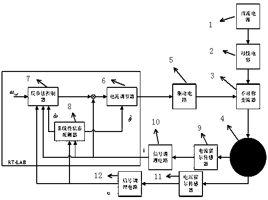
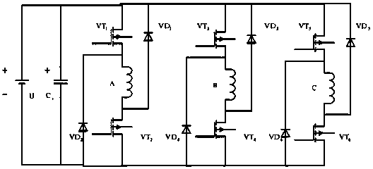
[0014] A position sensorless switched reluctance motor drive system, DC power supply 1, bus capacitor 2, asymmetric converter 3, switched reluctance motor 4, drive circuit 5, current regulator 6, backstepping controller 7, non Linear state observer 8, current Hall sensor 9, current signal conditioning circuit 10, voltage Hall sensor 11, voltage signal conditioning circuit 12, the DC power supply 1, the bus capacitor 2, the asymmetric converter 3 The switched reluctance motor 4 is connected in sequence, and the switched reluctance motor 4 respectively feeds back information to the current Hall sensor 9 and the associated voltage Hall sensor 11, and the current Hall sensor 9 is connected to the current signal conditioning Circuit 10, the voltage Hall sensor 11 is connected to a voltage signal conditioning circuit 12, the current signal conditioning circuit 10 and the voltage signal conditioning circuit 12 are connected to the backstepping controller 7, the backstepping control 7...


PUM

PropertyMeasurementUnit
Capacitanceaaaaaaaaaa

Abstract

A sensorless switch magnetic resistance motor-driven system belongs to the motor control field, and comprises a switch magnetic resistance motor, an asymmetric converter, a bus capacitor, a DC power supply, a driving circuit, a current regulator, a backstepping controller, a non-linear state observer, a current hall sensor, a current signal conditioning circuit, a voltage hall sensor, and a voltage signal conditioning circuit; the sensorless structure can increase the system stability; the non-linear state observer can monitor the stator-phase voltage and phase current so as to calculate therotor position, thus accurately determining the rotor position even the motor is under a high speed rotating state, reducing the system cost, and improving the driving precision.

Description

technical field [0001] The invention belongs to the field of motor control, in particular to a drive system of a position sensorless switched reluctance motor. Background technique [0002] Switched reluctance motor is the latest generation of stepless speed regulation system developed after frequency conversion speed regulation system and brushless DC motor speed regulation system. It integrates modern microelectronic technology, digital technology, power electronics technology, infrared photoelectric technology and modern electromagnetic technology. It is a high-tech integrated optical, mechanical and electrical integration of theory, design and production technology. It has simple structure, low cost, many controllable parameters, small starting current, large starting torque, high system efficiency and good braking. Excellent features such as energy recovery performance are widely used in various electronic and mechanical fields. In recent years, they have also been wide...

Claims


Application Information

Patent Timeline
IPC IPC(8): H02P6/182
CPCH02P6/182
Inventor 朱金荣夏长权陈卫峰
Owner 扬州汉龙电气有限公司
Learn More