A frame-type electromagnet rapid automatic assembly system

A frame-type electromagnet and automatic assembly technology, which is applied to assembly machines, devices for coating liquid on the surface, metal processing equipment, etc., can solve the problems of electromagnet quality degradation, quality cannot be guaranteed, and cannot be used normally, so as to prevent Installation deviation, compact structure, and the effect of improving assembly quality

Active Publication Date: 2019-04-23
陈志伟
View PDF11 Cites 0 Cited by
  • Summary
  • Abstract
  • Description
  • Claims
  • Application Information

AI Technical Summary

Problems solved by technology

[0002] The electromagnet consists of five parts: a square tube, an iron core winding, a guide rod, a spring and a top cover. The same magnetism as a magnet makes the iron core assimilate with adsorption force, and can absorb the guide rod to protrude or retract in the square tube. Most of the existing frame electromagnets are assembled manually. Due to the instability of manual assembly, the During the process of installing the iron core winding in the square tube and inserting the guide rod from one end of the square tube, the installation of the iron core winding and the guide rod will be deviated due to the inability to locate, which will directly lead to the decline in the quality of the electromagnet, which cannot be used normally, and manual The assembly time is long, the efficiency is low, and the quality cannot be guaranteed. At this time, a frame-type electromagnet fast automatic assembly system is needed to solve the above problems

Method used


Image

  • A frame-type electromagnet rapid automatic assembly system
  • A frame-type electromagnet rapid automatic assembly system
  • A frame-type electromagnet rapid automatic assembly system

Examples


Embodiment 1

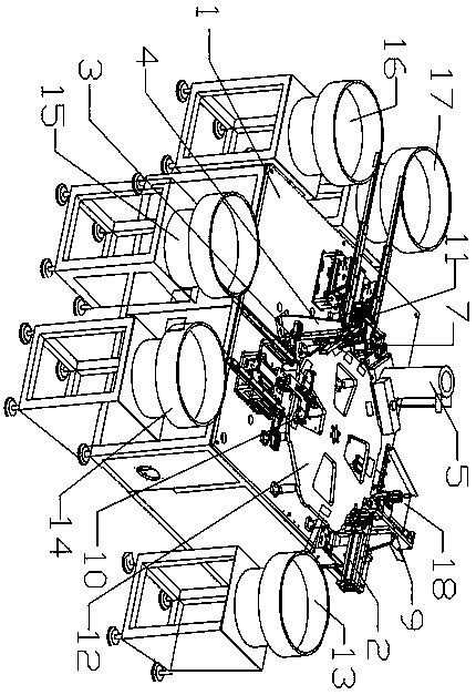
[0032] Such as figure 1 Shown, embodiment 1 of the present invention is:

[0033] A frame-type electromagnet rapid automatic assembly system, including a frame 1, an electric control device is arranged under the frame 1, a main turntable 12 is arranged on the frame 1, and a plurality of square tubes for fixing are arranged on the upper part of the main turntable 12 The lower part of the main turntable 12 is provided with a cam splitter for controlling the rotation of the main turntable 12, and the periphery of the main turntable 12 is provided with a square tube feeding device 2, an iron core winding feeding device 10, a guide Rod feeding device 3, glue dispensing device for bonding the iron core winding to the square tube 4, spring feeding device 11, top cover feeding device 7, welding device for welding the top cover and the upper wall of the square tube 5 and finished product receiving device 9 and above-mentioned each device is all provided with photoelectric sensor; The ...


PUM


Abstract

The invention relates to a frame-type electromagnet rapid automatic assembling system. The frame-type electromagnet rapid automatic assembling system comprises a rack, electric control equipment is arranged below the rack, the rack is provided with a main rotating disc, and the upper portion of the main rotating disc is provided with a plurality of positioning seats; the periphery of the main rotating disc is sequentially provided with a square tube feeding device, an iron core winding feeding device, a guide rod feeding device, a dispensing device, a spring feeding device, a top cover feedingdevice, a welding device and a finished product receiving device in the rotating direction of the main rotating disc; the side face of the spring feeding device is further provided with a winding detecting device and a defective recovery device; and a photoelectric sensing sheet is further arranged at the outer edge, close to the positioning seats, of the main rotating disc. According to the frame-type electromagnet rapid automatic assembling system, a frame-type electromagnet is assembled in a fully-mechanized mode, iron core winding and guide rod mounting deviation are prevented, and the assembling quality is improved; the round main rotating disc is used, the structure is compact, the working process is shortened, and the assembling efficiency is improved; and the winding detecting device and the defective recovery device are matched for operation so as to inspect the quality of iron core winding and remove defectives, and the situation that the defectives flow into the market in amixing mode is avoided.

Description

technical field [0001] The invention relates to the technical field of electromagnet assembly, in particular to a frame-type electromagnet rapid automatic assembly system. Background technique [0002] The electromagnet consists of five parts: a square tube, an iron core winding, a guide rod, a spring and a top cover. The same magnetism as a magnet makes the iron core assimilate with adsorption force, and can absorb the guide rod to protrude or retract in the square tube. Most of the existing frame electromagnets are assembled manually. Due to the instability of manual assembly, the During the process of installing the iron core winding in the square tube and inserting the guide rod from one end of the square tube, the installation of the iron core winding and the guide rod will be deviated due to the inability to locate, which will directly lead to the decline in the quality of the electromagnet, which cannot be used normally, and manual The assembly time is long, the effi...

Claims


Application Information

Patent Timeline
Patent Type & Authority Patents(China)
IPC IPC(8): B23P21/00B23P19/00B05C5/02B05C11/10
CPCB05C5/0212B05C11/1002B05C11/1018B23P19/007B23P21/006
Inventor 陈志伟
Owner 陈志伟
Why Eureka
Try Eureka