Heavy oil hydrotreating method
A treatment method, heavy oil hydrogenation technology, which is applied in the fields of hydrogenation treatment process, hydrocarbon oil treatment, petroleum industry, etc., can solve the problems of reducing coke yield, limited, etc., and achieves extended operation period, simple process, metal removal/accommodation The effect of ability improvement
- Summary
- Abstract
- Description
- Claims
- Application Information
AI Technical Summary
Problems solved by technology
Method used
Image
Examples
Embodiment 1
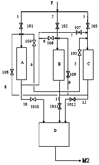
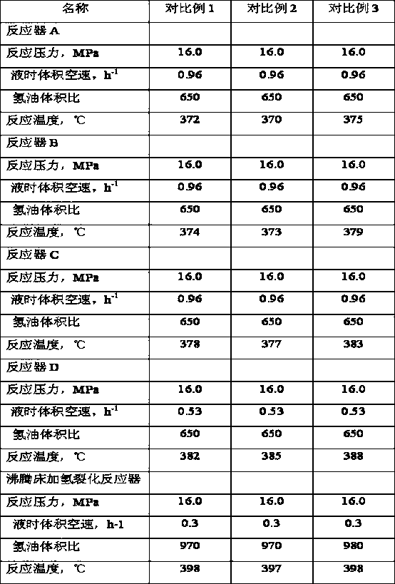
[0089] Raw material A is used as described in Example 1, and its properties are shown in Table 1. Raw material A is separated to obtain light fraction and heavy fraction with a cut point of 530°C. After the heavy fraction is processed by the solvent deasphalting unit, deasphalted oil and deoiled asphalt are obtained. The operating conditions of solvent deasphalting are shown in Table 8. The resulting deasphalted oil and light fractions are sent to the hydropretreatment reaction zone. The total catalyst loading, feed properties and feed amount of the hydropretreatment reactor A, hydrogenation pretreatment reactor B, and hydrogenation pretreatment reactor C are exactly the same, and the hydrogenation pretreatment reactor A, The catalysts of hydroprocessing reactor B, hydroprocessing reactor C, and hydroprocessing reactor D are loaded according to the mode in Table 2, and the hydroprocessing reactor A, hydroprocessing reactor B, The operating conditions of hydrogenation pretrea...
Embodiment 2
[0091] Raw material B is used as described in Example 2, and its properties are shown in Table 1. Feedstock B was separated into light and heavy fractions with a cut point of 538°C. The heavy fraction is processed through a solvent deasphalting unit to obtain deasphalted oil and deoiled asphalt; see Table 8 for the operating conditions of solvent deasphalting. The resulting deasphalted oil and light fractions are sent to the hydropretreatment reaction zone. The total catalyst loading, feed properties and feed amount of the hydropretreatment reactor A, hydrogenation pretreatment reactor B, and hydrogenation pretreatment reactor C are exactly the same, and the hydrogenation pretreatment reactor A, The catalysts of hydroprocessing reactor B, hydroprocessing reactor C, and hydroprocessing reactor D are loaded according to the mode in Table 2, and the hydroprocessing reactor A, hydroprocessing reactor B, The operating conditions of hydrogenation pretreatment reactor C, hydrotreat...
Embodiment 3
[0093]Raw material C is used as described in Example 3, and its properties are shown in Table 1. Feedstock C is separated to obtain light fraction and heavy fraction with a cut point of 550°C. The heavy fraction is processed through a solvent deasphalting unit to obtain deasphalted oil and deoiled asphalt; see Table 8 for the operating conditions of solvent deasphalting. The resulting deasphalted oil and light fractions are sent to the hydropretreatment reaction zone. The total catalyst loading, feed properties and feed amount of the hydropretreatment reactor A, hydrogenation pretreatment reactor B, and hydrogenation pretreatment reactor C are exactly the same, and the hydrogenation pretreatment reactor A, The catalysts of hydroprocessing reactor B, hydroprocessing reactor C, and hydroprocessing reactor D are loaded according to the mode in Table 2, and the hydroprocessing reactor A, hydroprocessing reactor B, The operating conditions of hydrogenation pretreatment reactor C,...
PUM
 Abstract
Description
Claims
Application Information
 - R&D
- Intellectual Property
- Life Sciences
- Materials
- Tech Scout
- Unparalleled Data Quality
- Higher Quality Content
- 60% Fewer Hallucinations
Browse by: Latest US Patents, China's latest patents, Technical Efficacy Thesaurus, Application Domain, Technology Topic, Popular Technical Reports.
© 2025 PatSnap. All rights reserved.Legal|Privacy policy|Modern Slavery Act Transparency Statement|Sitemap|About US| Contact US: help@patsnap.com


