Preparation method of spinning structure thermoelectric conversion device

A technology of thermoelectric conversion devices and textile structures, which is applied in the manufacture/processing of thermoelectric devices, thermometers using directly heat-sensitive electrical/magnetic components, and textiles, etc., can solve uneven structure control, single variety, and high low cost Efficiency and other issues, to achieve the effect of a wide range of application prospects

Inactive Publication Date: 2018-06-01
DONGHUAJINGYUE SUZHOU TEXTILE TECH RES CO LTD
View PDF3 Cites 6 Cited by
  • Summary
  • Abstract
  • Description
  • Claims
  • Application Information

AI Technical Summary

Problems solved by technology

[0005] In view of the above problems, the purpose of the present invention is to provide a low-cost and high-efficiency thermoelectric power generation structural fabric design and its weaving method based on the thermoelectric yarn scale, which overcomes the above-mentioned numerous raw materials, complex structure, difficult actual manufacturing process, and single variety. The shortcomings of textile structural materials such as uneven structure control lead to low thermoelectric conversion efficiency, and the generated current is along the thickness direction of the fabric, which has wide application prospects

Method used


Image

  • Preparation method of spinning structure thermoelectric conversion device
  • Preparation method of spinning structure thermoelectric conversion device
  • Preparation method of spinning structure thermoelectric conversion device

Examples


Embodiment 1

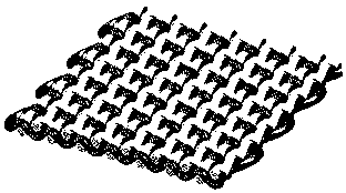
[0020] figure 2 It is a schematic diagram of a thermoelectric fabric in Example 1 of the present invention. The thermoelectric fabric in this example is a plain weave structure. The insulating warp yarns are arranged on the small prototype machine along the fabric forming direction, and a PN type thermoelectric yarn and an insulating yarn are introduced alternately. The thread is used as the weft yarn, and the desired fabric is formed after several cycles, such as figure 2 As shown, a constant current is generated by applying a temperature difference in the thickness direction of the fabric

[0021] In this embodiment, the forming looms used include but are not limited to small prototype looms; the yarns used are all soft, strong and weavable yarns.

Embodiment 2

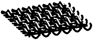
[0023] image 3 It is a schematic diagram of a thermoelectric fabric in Example 2 of the present invention. The textile structure thermoelectric power generation material in this example is a weft-knitted structure, using P-type thermoelectric yarns, N-type thermoelectric yarns, insulating yarns and thermoelectric yarns. P The type thermoelectric yarn and the N type thermoelectric yarn are alternately fed into the crochet needles of the knitting machine, and the desired fabric is formed after several cycles. Insulating and thermoelectric yarns are introduced after weaving. A constant current is generated by applying a temperature difference in the thickness direction of the fabric.

[0024] In this embodiment, the fabric forming mechanisms used include but should not be limited to knitting machines; the yarns used are all soft, strong and weavable yarns; on the one hand, the insulating yarns bear the transition of part of the temperature difference, and more importantly, To ...

Embodiment 3

[0026] Figure 4 It is a schematic diagram of the thermoelectric fabric structure of the third embodiment of the present invention. The textile structure thermoelectric power generation material in this embodiment is a three-dimensional orthogonal three-dimensional woven structure. Figure 4 This is a schematic diagram of the yarns used in this example. The insulating warp yarns are arranged on the three-dimensional loom according to a certain warp density along the fabric forming direction, and a PN type thermoelectric yarn and insulating weft yarn are sequentially introduced. The number of weaving cycles is controlled according to the desired fabric length to obtain the desired fabric. A constant current is generated by applying a temperature difference across the thickness of the fabric.

[0027] In this implementation example, the fabric forming mechanism used should include but not limited to a three-dimensional loom; the yarns used are all soft, have a certain strength ...


PUM


Abstract

The invention provides a preparation method of a spinning structure thermoelectric conversion device. The spinning structure thermoelectric conversion device adopts one or more kinds of thermoelectricyarns as thermocouples of the thermoelectric electricity generation structure, elastic insulation yarn is adopted as a fabric body bearing part, and the thermoelectric yarn is woven into the thermoelectric electricity generation fabric structure through a traditional spinning technology by means of the characteristic that weft and warp of the fabric are interwoven and stacked; by changing the fabric interweaving structure, the thermoelectric yarn placement position and the length of the thermocouples, the thermoelectric transmission performance and the body bearing performance are changed, and the device can be widely and flexibly applied to the fields of motion health, medical intelligent clothing, intelligent homes, wearable touch screens, electronics, automobiles, buildings and the like.

Description

technical field [0001] The invention relates to the field of thermoelectric power generation, in particular to the structure and preparation method of P-type, N-type and PN-type thermoelectric yarns and thermoelectric power generation fabrics thereof. Background technique [0002] Thermoelectric fabrics are green energy materials that can directly convert thermal energy into electrical energy. The characteristics of processing and energy conversion without other media have attracted widespread attention. [0003] Textiles are in close contact with the human body and can be used as excellent flexible carriers for various micro-nano electronic devices. Combining fabric and thermoelectricity to develop fabric thermoelectric devices can provide energy for micro-nano electronic devices. At the same time, the three-dimensional textile structure has the characteristics of one-time molding and excellent mechanical properties. It has been applied in some fields. The combination of ...

Claims


Application Information

Patent Timeline
Patent Type & Authority Applications(China)
IPC IPC(8): D03D15/00D04B1/14D04B21/00D04C1/02D03D25/00D03D15/50D03D15/52D03D15/56
CPCD03D25/005D04B1/14D04B21/00D04C1/02D03D15/50D03D1/0088H10N10/01H10N10/17D10B2401/16G01K7/02
Inventor 郑贤宏郑圆圆文琦付文丽许庆丽毛宁陈文翀覃小红邱夷平陈霞张坤
Owner DONGHUAJINGYUE SUZHOU TEXTILE TECH RES CO LTD
Why Eureka
Try Eureka