
Insulator leakage current and zero value detection device

A leakage current and zero-value detection technology, which is applied in the direction of measuring devices, measuring electricity, and measuring electrical variables, can solve the problems of inability to carry out live operation, quantitative analysis, and heavy detection workload, etc., to achieve live detection, structure Simple, easy-to-use effect

Inactive Publication Date: 2018-06-01
STATE GRID CHONGQING ELECTRIC POWER CO ELECTRIC POWER RES INST +2
View PDF7 Cites 3 Cited by
  • Summary
  • Abstract
  • Description
  • Claims
  • Application Information

AI Technical Summary

Problems solved by technology

[0006] The insulation resistance measurement method is used to detect zero-value insulators with high accuracy, but the detection workload is large, the cost is high, and live operation cannot be performed
[0007] The spark gap method is to judge whether it is a zero-value insulator by observing the sparks generated in the air gap between the metal steel fork and the steel cap. This method is simple in principle and easy to operate, but it is only a qualitative method due to many factors affecting gap discharge. Quantitative analysis cannot be performed; if there are multiple low-value or zero-value insulators in a string of insulators, the spark gap method may cause flashover of the insulator string
[0008] Infrared imaging method is a method of detecting zero-value insulators based on temperature distribution changes using infrared thermal imaging cameras. However, this method mainly relies on experience to recognize infrared images for insulator zero-value detection, and there is a certain degree of blindness.

Method used


Image

  • Insulator leakage current and zero value detection device
  • Insulator leakage current and zero value detection device

Examples


Embodiment Construction

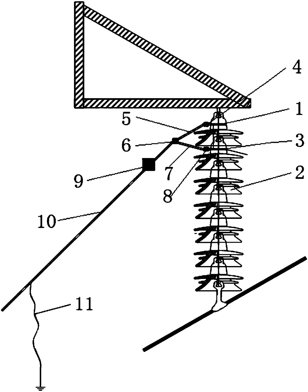
[0038] The core of the invention is to provide an insulator leakage current and zero value detection device, which has a simple structure and is easy to use, and can realize live detection of insulator voltage signals and current signals.

[0039] In order to enable those skilled in the art to better understand the solution of the present invention, the present invention will be further described in detail below in conjunction with the accompanying drawings and specific embodiments.

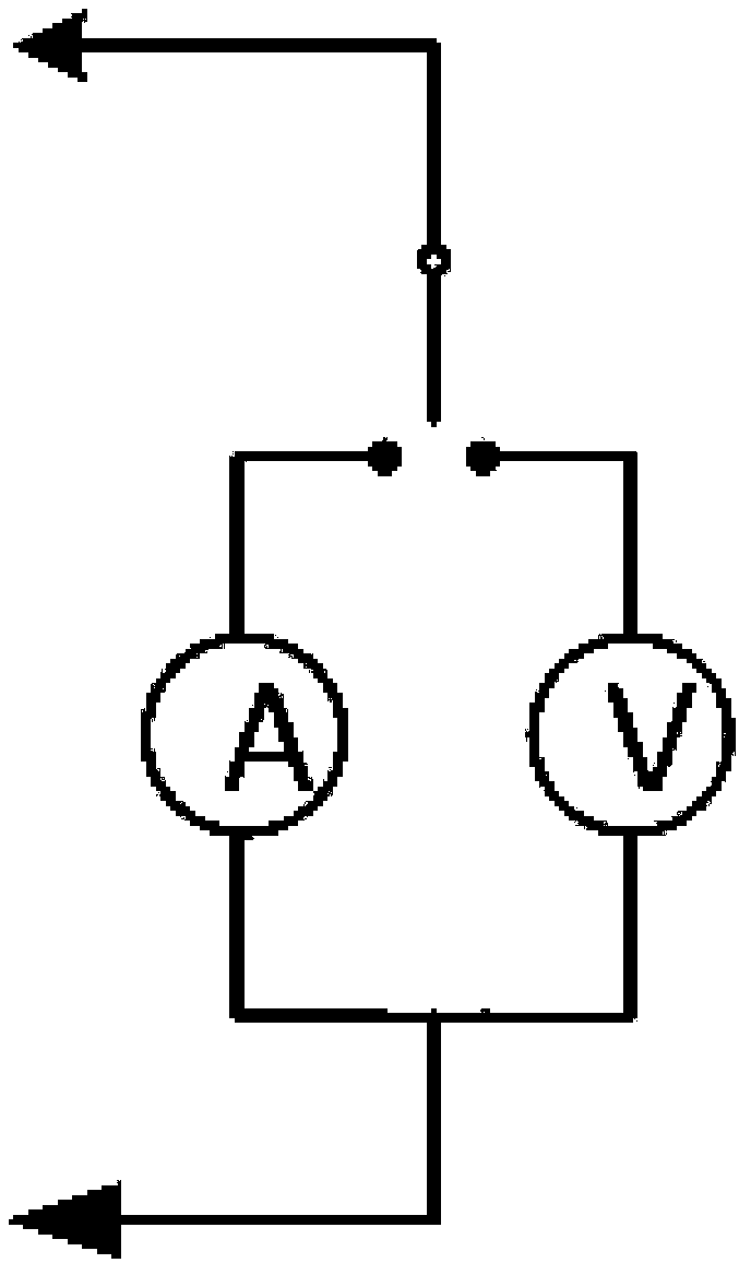
[0040]The present invention provides an insulator leakage current and zero value detection device, including an insulating rod 10, the insulating rod 10 is made of insulating material, and the insulating rod 10 should have good insulation to ensure the personal safety of live workers, preferably It is made of glass fiber reinforced plastic epoxy resin insulating rod, or made of rubber material; the top end of the insulating rod 10 is equipped with a clamping assembly for clamping two insulators 2 ...


PUM


Abstract

The invention provides an insulator leakage current and zero value detection device comprising an insulation rod. The top of the insulation rod is provided with a clamping assembly for clamping two insulators arranged longitudinally. The insulator leakage current and zero value detection device also comprises a controllable joint assembly disposed between the insulation rod and the clamping assembly and used for adjusting the position of the clamping assembly, and a control assembly disposed on the insulation rod, connected with the controllable joint assembly, and used for controlling the clamping assembly to measure and store the current and the voltage between the two insulators and to mutually convert the current and voltage signals. In addition, a ground controller is installed on theground to send a wireless current signal or a wireless voltage signal to be measured to the control assembly and to receive a measurement result from the control assembly. The detection device is simple in structure and is easy to operate, can detect the insulator zero-value voltage and the insulator string current in an alive state only through the form of wireless transmission, and satisfies the measurement requirements of two different electrical signals.

Description

technical field [0001] The invention relates to the field of electric system leakage current and zero value insulator detection, in particular to an insulator leakage current and zero value detection device. Background technique [0002] The division of pollution levels in the power system (contaminated area distribution map) is the basic specification for power design, operation and maintenance, and anti-pollution flashover technical management. The enterprise standard Q-GDW 152-2006 of State Grid Corporation and IEC60815 also consider the influence of salt density and dust density when classifying pollution levels. The method recommended by IEC is also an important method widely used by my country's electric power operation departments to detect the pollution degree of insulators. However, the method of measuring the salt density and ash density of insulators to characterize the pollution degree of transmission lines mainly adopts traditional manual cleaning. In this method...

Claims


Application Information

Patent Timeline
IPC IPC(8): G01R31/12G01D21/02G08C17/02
CPCG01D21/02G01R31/1245G08C17/02
Inventor 吴高林周庆肖前波刘正发付启刚宋伟邓帮飞张海兵黄江晨夏磊孟宪吴志清王光明向洪彭姝迪毕茂强胡建林蒋兴良
Owner STATE GRID CHONGQING ELECTRIC POWER CO ELECTRIC POWER RES INST
Learn More