Numerical control device cutter wearing detection method based on cloud knowledge base and machine learning
A technology of tool wear and machine learning, which is applied in computer control, instruments, simulators, etc., can solve the problem that manual detection of tool wear cannot accurately obtain the amount of tool wear
- Summary
- Abstract
- Description
- Claims
- Application Information
AI Technical Summary
Problems solved by technology
Method used
Image
Examples
Embodiment 1
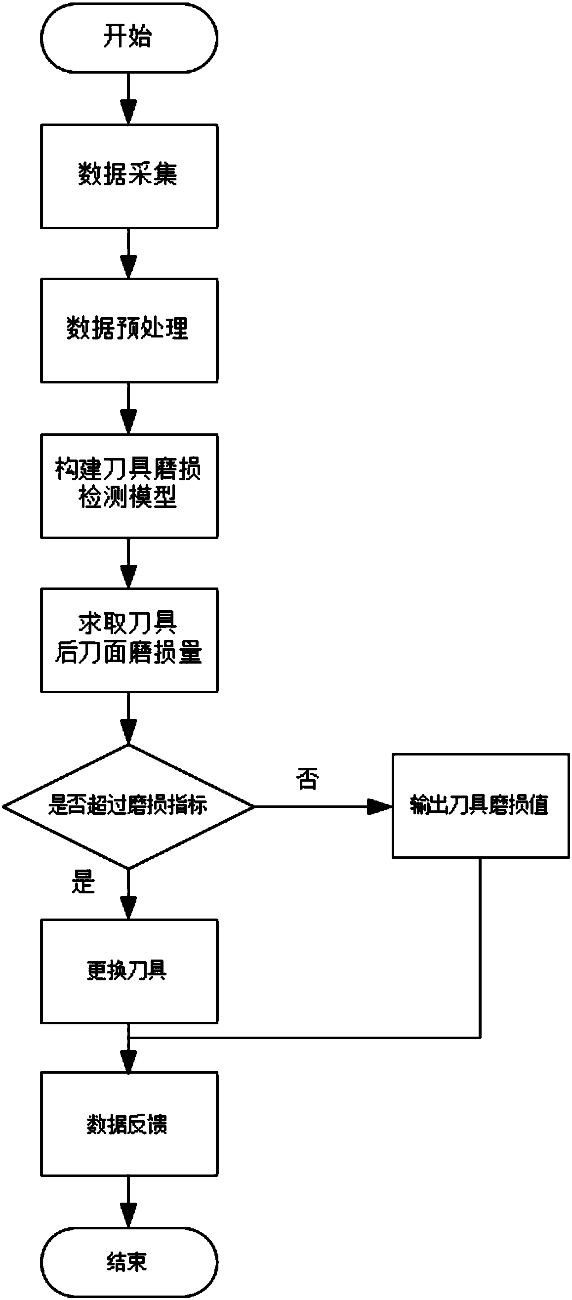
[0057] A tool wear detection method for CNC equipment based on cloud knowledge base and machine learning, such as image 3 As shown, the method is applied to the local workshop, which includes several local CNC machine tools and local workshop servers respectively connected to several CNC machine tools, including:
[0058] A. Construct and train tool wear detection model
[0059] (1) Build a cloud knowledge base to form a distributed cluster system; the distributed cluster system can have the computing power of multiple computers, and can effectively realize the storage and processing of massive data.
[0060] (2) Collect the working condition data of the workshop and transmit them to the cloud knowledge base through the network. The cloud knowledge base groups and stores the working condition data; the working condition data includes workpiece information, tool information, and cutting parameters; the workpiece information includes working condition information number, workp...
Embodiment 2
[0066] According to a method for detecting tool wear of CNC equipment based on cloud knowledge base and machine learning described in Embodiment 1, the difference is that
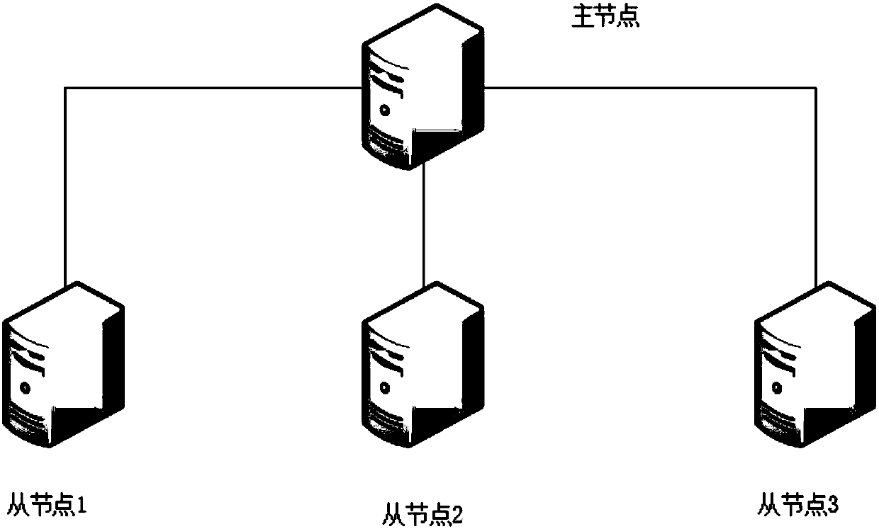
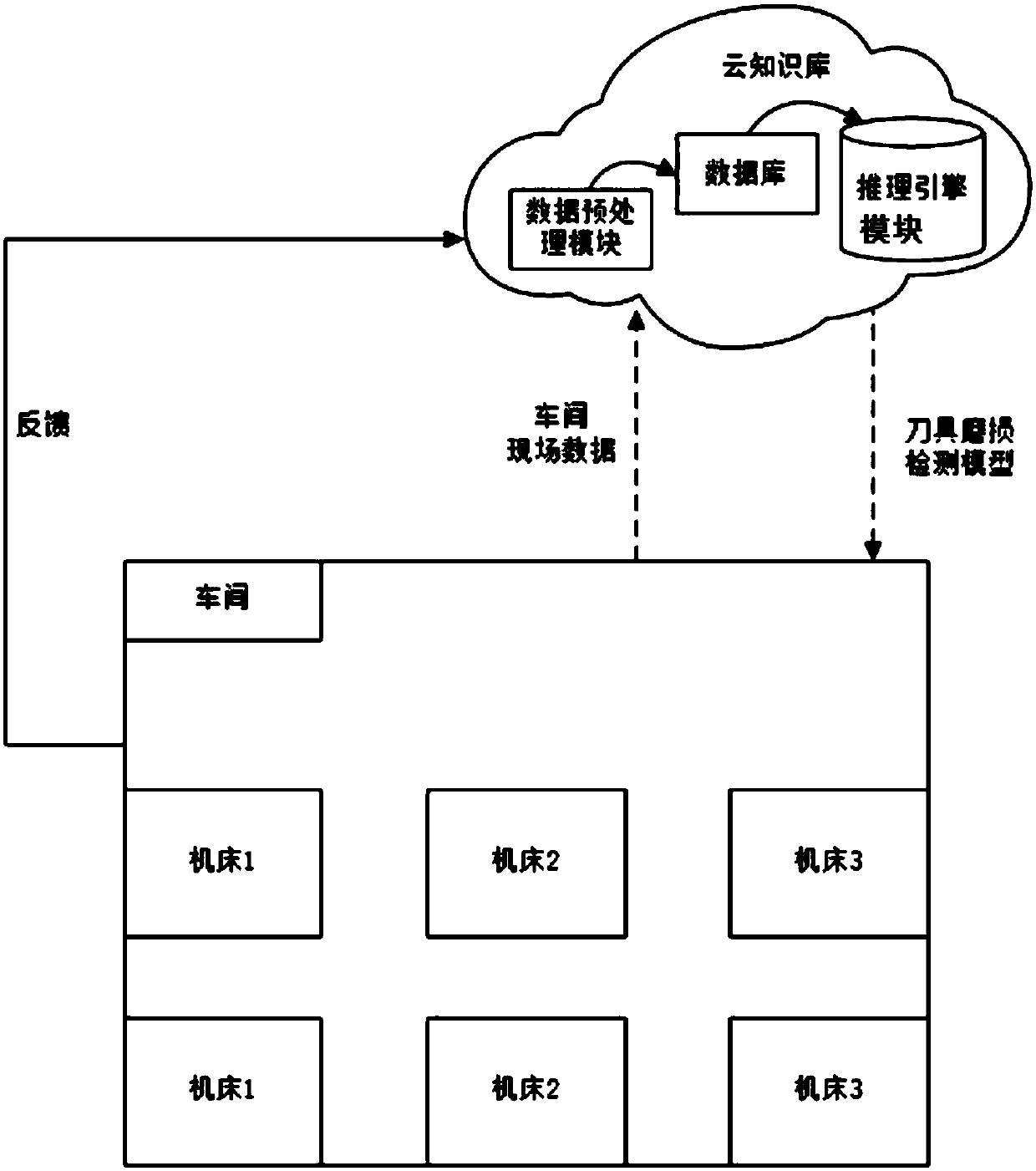
[0067] The cloud knowledge base is built using the Hadoop platform. The distributed cluster system includes four servers, one of which serves as the master node, and the other three servers serve as slave nodes (slave node 1, slave node 2, and slave node 3), forming a fully distributed Hadoop cluster environment such as figure 1 shown. The distributed cluster system can have the computing power of multiple computers, and can effectively realize the storage and processing of massive data. The server is a high performance computer. The cloud knowledge base is built on the workshop server, and forms a cloud knowledge base-NC machine tool system with each CNC machine tool in the workshop, such as figure 2 shown;
[0068] The cloud knowledge base includes a data preprocessing unit, a database and a reasonin...
Embodiment 3
[0073] According to a method for detecting tool wear of CNC equipment based on cloud knowledge base and machine learning described in Embodiment 2, the difference is that
[0074] Step (3), design the tool wear detection model, and use the support vector machine algorithm to train the tool wear detection model, such as Figure 4 shown, including:
[0075] a. Set input parameters, including workpiece information parameters, tool information parameters, and cutting parameters. The workpiece information parameters include workpiece material, workpiece geometric dimensions, workpiece machining surface roughness, and workpiece processing operations; the tool information parameters include tool material. , entering angle, rake angle, and relief angle; the cutting parameters include cutting speed, cutting amount, and feeding amount;
[0076] b. Set the output parameter as the tool flank wear amount;
[0077] c. According to the working condition information number, extract the data...
PUM
 Abstract
Description
Claims
Application Information
 - R&D
- Intellectual Property
- Life Sciences
- Materials
- Tech Scout
- Unparalleled Data Quality
- Higher Quality Content
- 60% Fewer Hallucinations
Browse by: Latest US Patents, China's latest patents, Technical Efficacy Thesaurus, Application Domain, Technology Topic, Popular Technical Reports.
© 2025 PatSnap. All rights reserved.Legal|Privacy policy|Modern Slavery Act Transparency Statement|Sitemap|About US| Contact US: help@patsnap.com


