Detector, depth measurement detector unit and function depth calculation method thereof

A depth measurement and detector technology, applied in the field of detectors and depth measurement detector units, can solve the problems of discontinuous interaction depth information, difficult to control uniformity, and long time consumption, and achieve continuous interaction depth information and reduce the realization of Difficulty and cost, good effect of time resolution

Inactive Publication Date: 2018-06-05
SHENZHEN INST OF ADVANCED TECH
View PDF17 Cites 1 Cited by
  • Summary
  • Abstract
  • Description
  • Claims
  • Application Information

AI Technical Summary

Problems solved by technology

[0005] The first object of the present invention is to provide a depth measurement detector unit, which aims to solve the problem of difficult scintillation crystal cutting techno

Method used


Image

  • Detector, depth measurement detector unit and function depth calculation method thereof
  • Detector, depth measurement detector unit and function depth calculation method thereof
  • Detector, depth measurement detector unit and function depth calculation method thereof

Examples


Embodiment 1

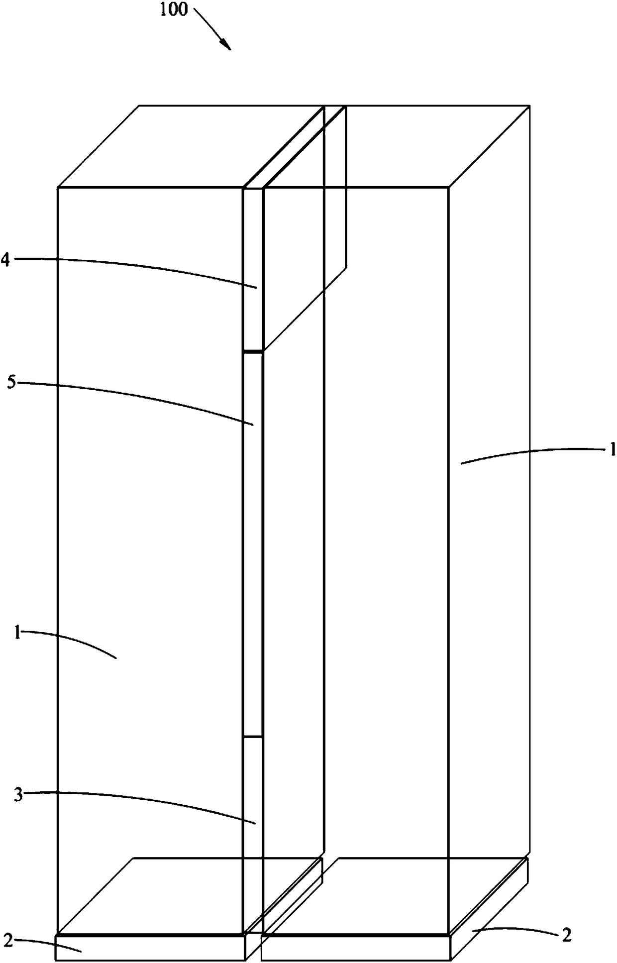
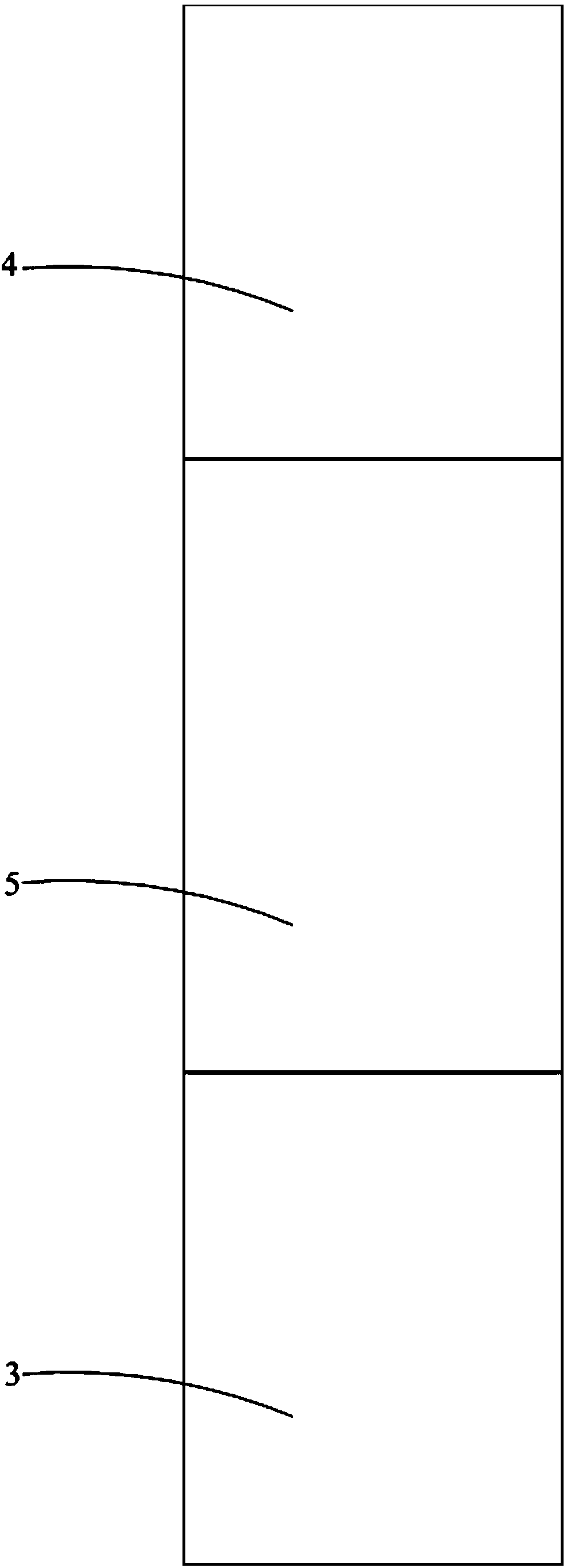
[0033] Such as Figure 1-3 As shown, the depth measurement detector unit 100 provided by Embodiment 1 of the present invention includes two scintillation crystals 1 arranged side by side at intervals and two photodetectors 2 arranged at intervals and arranged at one end of the two scintillation crystals 1 respectively. The gap between the scintillation crystals 1 includes a first layered space close to the photodetector 2, a second layered space away from the photodetector 2, and a third layered space between the first layered space and the second layered space. In the layered space, the first layered space is filled with the first reflective film 3 , the second layered space is filled with the optical coupler 4 , and the third layered space is filled with air 5 . The depth measurement detector unit 100 provided in this embodiment is coupled in different positions between two identical scintillation crystals 1 by using the first reflective film 3, the air 5 and the optical cou...

Embodiment 2

[0052] The difference between the depth measuring detector, the detector and the working depth calculation method of the depth measuring detector unit 100 provided in this embodiment and the first embodiment is that the filling material in the third layered space is different, which is specifically reflected in: Such as Figure 1-3 As shown, in Embodiment 1, the air 5 is completely filled in the third layered space, that is, the middle part between the two scintillation crystals 1 is not treated, and is only isolated by air 5; Figure 4 As shown, in this embodiment, the third layered space is filled with air 5 and the second reflective film 6, that is, the middle part between the two scintillation crystals 1 is separated by air 5 and a third reflective film is additionally added. membrane. In this embodiment, since different materials are also used to couple at different positions between two identical scintillation crystals 1, it is possible to distinguish the degree of ligh...


PUM


Abstract

The invention is applicable to the field of medical equipment, and discloses a depth measurement detector unit, a function depth calculation method for the depth measurement detector unit and a detector. The depth measurement detector unit includes two scintillation crystals arranged side by side and two photodetectors arranged at the ends of the two scintillation crystals respectively, a gap between the two scintillation crystals includes a first layered space close to the photodetectors, a second layered space far away from the photodetectors and a third layered space located between the first layered space and the second layered space. The first layered space is filled with a first reflective film, the second layered space is filled with an optical coupling body, and the third layered space is filled with air. According to the depth measurement detector unit, the depth is read through the single-ended photodetectors without complicated processing of the scintillation crystals, the achieving difficulty and cost of the detector function depth measurement are reduced, and the depth measurement detector unit has high depth resolution and time resolution and good consistency.

Description

technical field [0001] The invention relates to the field of medical equipment, in particular to a depth measurement detector unit, a method for calculating the working depth of the depth measurement detector unit and a detector with the depth measurement detector unit. Background technique [0002] PET (Positron Emission Tomography, Positron Emission Tomography) is an advanced nuclear medical imaging instrument. The detector is the core component of the PET system, which is used to detect the position where gamma rays occur, and is mainly composed of scintillation crystals and photodetectors. A silicon photomultiplier (SiPM) array is a type of photodetector commonly used in PET systems. The scintillation crystal of a PET detector is usually composed of many long crystals with small cross-sections. Due to the uncertainty of the depth of interaction (DOI) of gamma rays in the scintillation crystal, the resolution of the PET system will change when it deviates from the center...

Claims


Application Information

Patent Timeline
IPC IPC(8): A61B6/03
CPCA61B6/037A61B6/4208A61B6/4233
Inventor 邝忠华杨永峰王晓辉付鑫任宁胡战利桑子儒吴三赵斌清梁栋刘新郑海荣
Owner SHENZHEN INST OF ADVANCED TECH
Why Eureka
Try Eureka