Continuous cutting device

A technology of cutting equipment and cutting wheel, which is applied in the direction of shearing machine equipment, metal processing equipment, shearing device, etc., can solve the problems of low production efficiency and inability to automatically feed and cut pipe materials, and achieve high production efficiency and high automatic feeding and cutting Effect

Active Publication Date: 2018-06-05
宁波隆锐机械制造有限公司
View PDF6 Cites 9 Cited by
  • Summary
  • Abstract
  • Description
  • Claims
  • Application Information

AI Technical Summary

Problems solved by technology

[0005] The present invention intends to provide a continuous cutting device to overcome the problems in the prior art that the continuous automatic feeding and cutting of the pipe surrounding the coiler and low production efficiency cannot be performed.

Method used


Image

  • Continuous cutting device
  • Continuous cutting device
  • Continuous cutting device

Examples


Embodiment Construction

[0018] The present invention will be described in further detail below by means of specific embodiments:

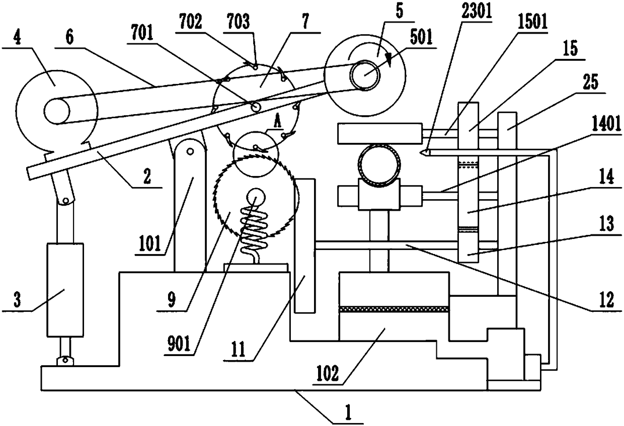
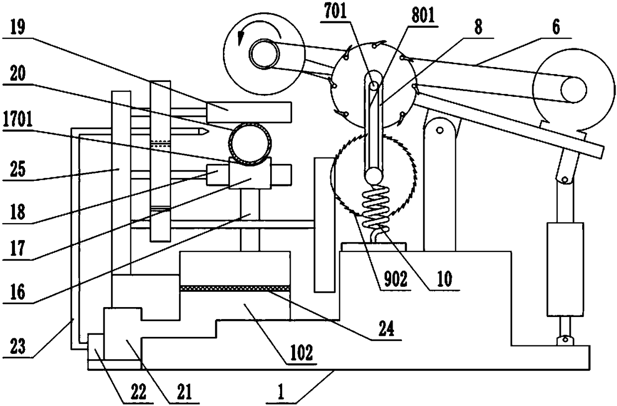
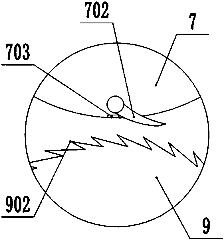
[0019] The reference signs in the accompanying drawings of the description include: frame 1, first support column 101, liquid collection tank 102, rotating plate 2, telescopic cylinder 3, cutting motor 4, cutting wheel 5, rotating shaft 501, belt 6, first rotation Wheel 7, first fixed shaft 701, ratchet 702, block 703, first sliding rod 8, sliding groove 801, second runner 9, second fixed shaft 901, ratchet 902, elastic support 10, first Transmission wheel 11, first transmission shaft 12, second transmission wheel 13, third transmission wheel 14, second transmission shaft 1401, fourth transmission wheel 15, third transmission shaft 1501, second support column 16, transmission rail 17, Arc groove 1701, cutting groove 1702, lower roller 18, upper roller 19, pipe material 20, liquid sump 21, pump 22, nozzle 23, liquid spray port 2301, filter screen 24, second support column ...


PUM


Abstract

The invention relates to the technical field of machining equipment, and discloses a continuous cutting device which comprises a rack with a first supporting stand column. A rotating plate is arrangedon the first supporting stand column, a telescopic cylinder is hinged to one end of the rotating plate, the telescopic cylinder and the rack are fixedly connected, a cutting wheel is installed on therotating plate, a first rotating wheel is connected to the rotating plate, a second rotating wheel is connected to the first rotating wheel, a first transmission wheel is connected to the second rotating wheel, the first transmission wheel is connected with a second transmission wheel, a third transmission wheel is connected to the second transmission wheel, a fourth transmission wheel is connected to the third transmission wheel, a lower roller is connected to the third transmission wheel, an upper roller is connected to the fourth transmission wheel, and a transmission rail is arranged on one side of the lower roller. Due to telescoping of the telescopic cylinder, the rotating plate is driven to turn over, in the process that the rotating plate is turned over, the upper roller and the lower roller drive tubes to move in a transmission rail, and the tubes are cut by a cutting wheel. The continuous cutting device has the advantage that the tubes surrounding in a tube coiler can be continuously cut.

Description

technical field [0001] The invention relates to the technical field of machining equipment, in particular to a cutting equipment. Background technique [0002] In the process of mechanical equipment processing, the cutting of pipes is usually involved, and the long pipes are cut into the required size according to the production requirements, so as to carry out the next production process. [0003] In the cutting process of the existing cutting equipment, especially when cutting the pipe surrounding the coiler, the pipe is usually pushed to the cutting knife by manual or external equipment for cutting, and the cutting is continued after the cutting is completed. The pipe is pushed towards the cutting knife for cutting until the pipe is cut. [0004] Although the above-mentioned technical solution realizes the cutting of the pipe material to a certain extent, it cannot perform continuous automatic feeding and cutting of the pipe material surrounding the coiler, and the produ...

Claims


Application Information

Patent Timeline
Patent Type & Authority Applications(China)
IPC IPC(8): B23D21/04B23D33/04B23Q1/25B23Q11/10
CPCB23D21/04B23D33/04B23Q1/25B23Q11/1069
Inventor 项文增
Owner 宁波隆锐机械制造有限公司
Why Eureka
Try Eureka