Dust removal ash conveying device and method for blast furnace

A blast furnace dust removal and conveying device technology, which is applied in conveying bulk materials, blast furnaces, conveyors, etc., can solve the problems of large power consumption, complex structure, and many failure points, and achieves recycling, high efficiency in conveying ash, and high operational efficiency. low cost effect

Pending Publication Date: 2018-06-05
MCC CAPITAL ENGINEERING & RESEARCH
View PDF14 Cites 7 Cited by
  • Summary
  • Abstract
  • Description
  • Claims
  • Application Information

AI Technical Summary

Problems solved by technology

Pneumatic ash conveying gas has the following problems: 1. Due to the application of warehouse pumps and fans in the process of ash conveying, it needs to consume a lot of electric energy; 2. The structure is complex and there are many fault points, which is easy to cause gas leakage; Blast furnace ash, poor fluidity, difficult for this system to deal with
The problems of this device: 1. The separation of the mortar is not realized, which is not conducive to the transportation of the dust; 2. The recycling of water is not considered, which is not suitable for the development of circular economy.

Method used


Image

  • Dust removal ash conveying device and method for blast furnace
  • Dust removal ash conveying device and method for blast furnace

Examples


Embodiment approach 1

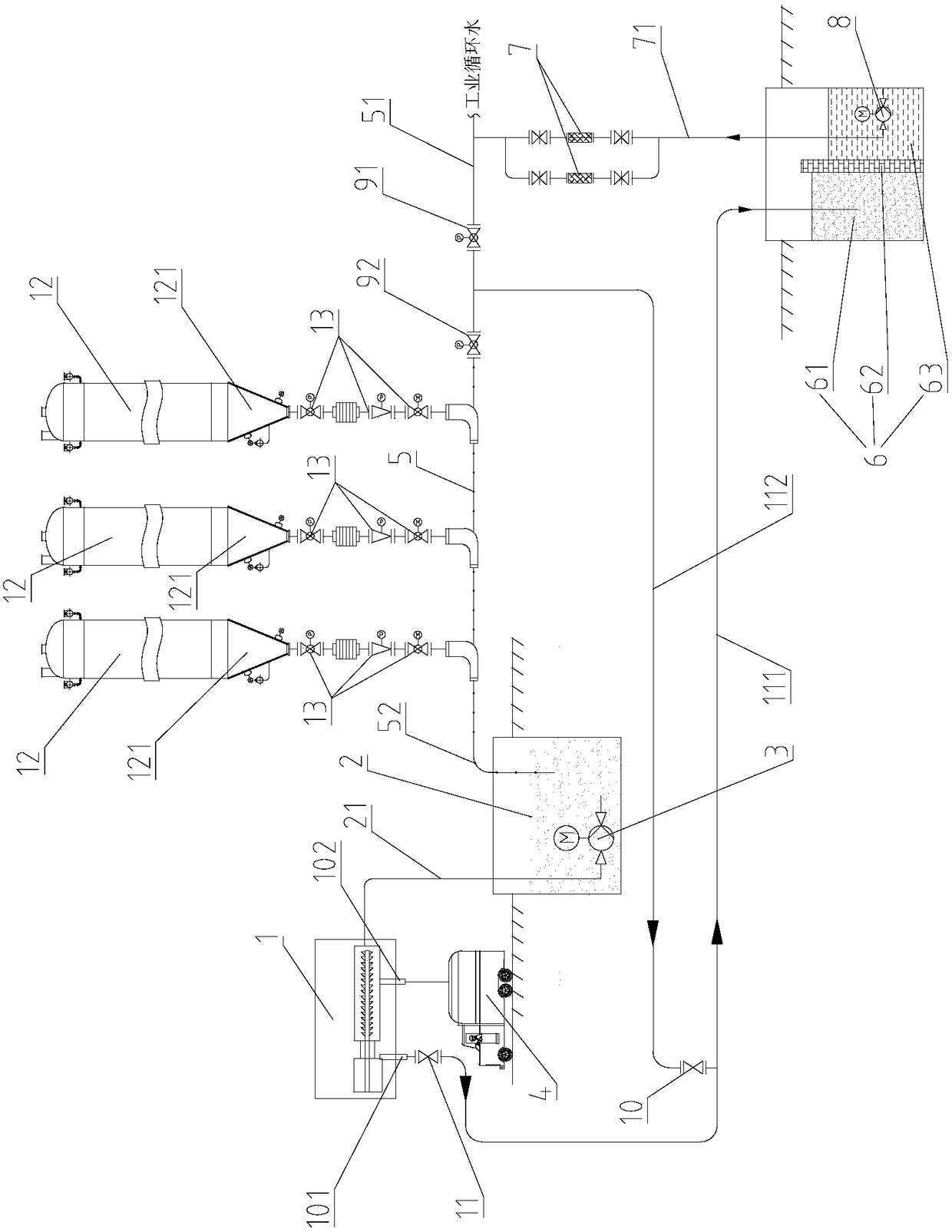
[0036] Such as figure 1 As shown, the present invention provides a blast furnace dust removal ash delivery device, comprising: a plurality of dust collectors 12 connected in parallel on an ash delivery pipeline 5, the first end 51 of the ash delivery pipeline 5 is connected with an industrial circulating water pipeline; mud pool 2 , which is connected to the second end 52 of the ash delivery pipeline 5, the first mud pump 3 is provided in the mud pool 2; the mud-water separation mechanism 1 is connected to the first mud pump 3 by the mud delivery pipeline 21, and the mud-water separation mechanism 1 has Water outlet 101 and mud outlet 102; Water recovery mechanism, it comprises settling tank 6 and the second mud pump 8 that is positioned at settling tank 6, settling tank 6 links to each other with the water outlet 101 of muddy-water separation mechanism 1 by outlet pipeline 111, the first The second mud pump 8 is connected with the first end 51 of the ash conveying pipeline 5 ...

Embodiment approach 2

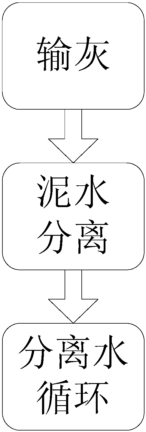
[0048] Such as figure 1 and figure 2 As shown, the present invention also provides a blast furnace dust removal method, which adopts the blast furnace dust removal device of the first embodiment. The working principle and beneficial effect of the blast furnace dust removal device are the same as those of the first embodiment, and are not repeated here repeat. The blast furnace dedusting ash conveying method comprises the following steps:

[0049] Step A, ash conveying: convey the collected furnace ash to the ash conveying pipeline 5 through a plurality of dust collectors 12, and then convey the furnace ash in the ash conveying pipeline 5 through the industrial circulating water in the industrial circulating water pipeline to In the mud pool 2, furnace ash and industrial circulating water are mixed in the mud pool 2 to form mud. The blast furnace dust removal method of the present invention uses industrial circulating water to transport the furnace ash, does not need to use...


PUM


Abstract

The invention provides dust removal ash conveying device and method for a blast furnace. According to the dust removal ash conveying device for the blast furnace, a plurality of dust removers are connected to an ash conveying pipeline in parallel, and the first end of the ash conveying pipeline is connected with an industrial cyclic water pipeline; a mud sump is connected to the second end of theash conveying pipeline, and a first mud pump is arranged in the mud sump; a mud-water separation mechanism is connected with the first mud pump through a mud conveying pipeline, and the mud-water separation mechanism is provided with a water outlet and a mud outlet; and a water recovery mechanism comprises a sedimentation tank and a second mud pump located in the sedimentation tank, the sedimentation tank is connected with the water outlet of the mud-water separation mechanism through a water outlet pipeline, and the second mud pump is connected with the first end of the ash conveying pipelinethrough a recovery pipeline. According to the dust removal ash conveying device and method for the blast furnace, furnace ash is conveyed in a manner of mixing industrial cyclic water with the furnace ash, so that blockage of the ash conveying pipeline can be avoided, and flying dust and pollution are avoided; moreover, the cyclic water in mud can be separated well; and the dust removal ash conveying device and method for the blast furnace are safe and environment-friendly, high in ash conveying efficiency, low in cost, and capable of realizing cyclic use of water.

Description

technical field [0001] The invention relates to a conveying device and method for blast furnace dedusting ash, in particular to a conveying device and method for blast furnace dedusting ash in the field of metallurgical industry. Background technique [0002] In recent years, my country's iron and steel enterprises have put forward higher and higher requirements for energy conservation and emission reduction. Cost control, clean production, and comprehensive utilization of resources are being widely concerned by various enterprises. It is stipulated in relevant industry standards that iron and steel enterprises should take developing circular economy, promoting clean production, saving energy, protecting ecological environment, improving economic efficiency and taking the road of sustainable development as the basic principles of operation. [0003] The blast furnace ash generated during the blast furnace smelting process is filtered through the bag filter and collected in t...

Claims


Application Information

Patent Timeline
Patent Type & Authority Applications(China)
IPC IPC(8): B65G53/30C02F9/02
CPCB65G53/30C02F1/001C02F1/38C21B5/007F27B1/18B01D46/023B01D45/12
Inventor 张红磊朴俊默王亚楠董艳苹张传波任乐瞿华
Owner MCC CAPITAL ENGINEERING & RESEARCH
Why Eureka
Try Eureka