Data center immersed-type liquid-cooling cabinet based on heat pipe technology

A data center and immersion technology, applied in the direction of cooling/ventilation/heating transformation, electrical components, electrical equipment construction parts, etc., can solve the problem of increasing the energy consumption of the air conditioning system, the increase of the heat dissipation energy consumption of the data center, and the temperature distribution of the heat dissipation system Uneven etc.

Inactive Publication Date: 2018-06-05
CENT SOUTH UNIV
View PDF8 Cites 20 Cited by
  • Summary
  • Abstract
  • Description
  • Claims
  • Application Information

AI Technical Summary

Problems solved by technology

The traditional cabinet cooling system adopts the air-conditioning air-cooling system, which has the following obvious defects: First, due to the poor heat transfer performance of the air, a lower air supply temperature is required to ensure the normal operation of high-heat-density servers, which will increase the air-conditioning system. The operating energy consumption of the existing data center will increase the energy consumption of heat dissipation; secondly, due to the small space in the cabinet and the poor air flow organization, it is easy to cause local high temperature points in the cabinet, which will affect the safe operation of IT equipment such as servers; Local hotspots often increase the air supply volume of the air conditioner and reduce the air supply temperature, resulting in a further increase in energy c

Method used


Image

  • Data center immersed-type liquid-cooling cabinet based on heat pipe technology
  • Data center immersed-type liquid-cooling cabinet based on heat pipe technology
  • Data center immersed-type liquid-cooling cabinet based on heat pipe technology

Examples


Embodiment Construction

[0031] Specific embodiments of the present invention will be described in detail below in conjunction with the accompanying drawings. It should be understood that the specific embodiments described here are only used to illustrate and explain the present invention, and are not intended to limit the present invention.

[0032] In the present invention, unless otherwise specified, the orientation words included in the term such as "up, down, left, right, front, back, inside and outside" only represent the orientation of the term in the normal use state, or the common name understood by those skilled in the art. , and should not be construed as a limitation of this term.

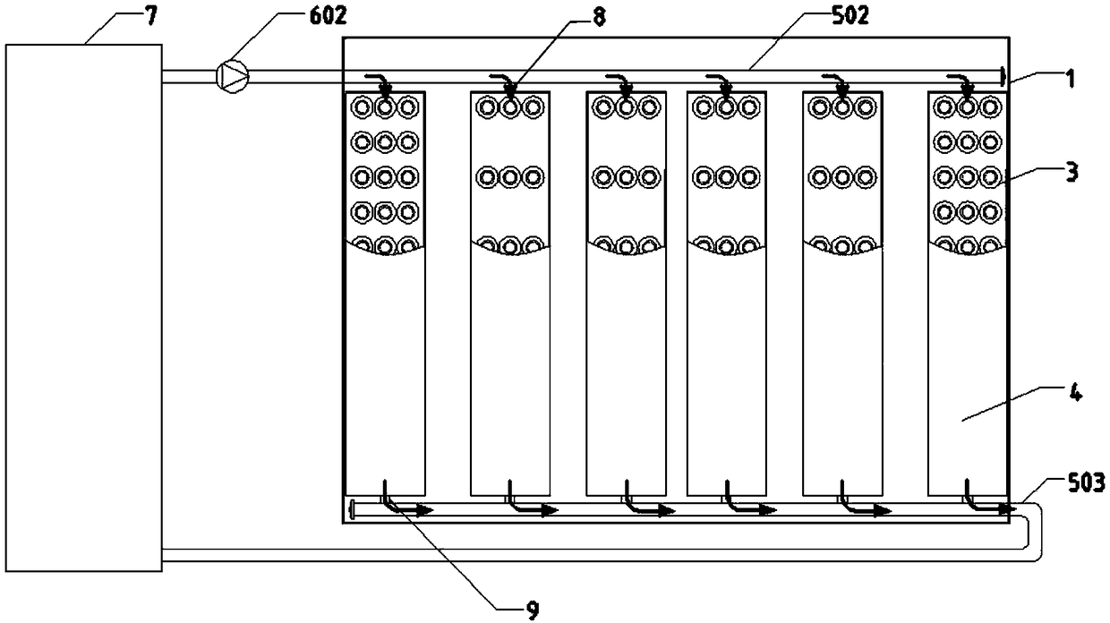
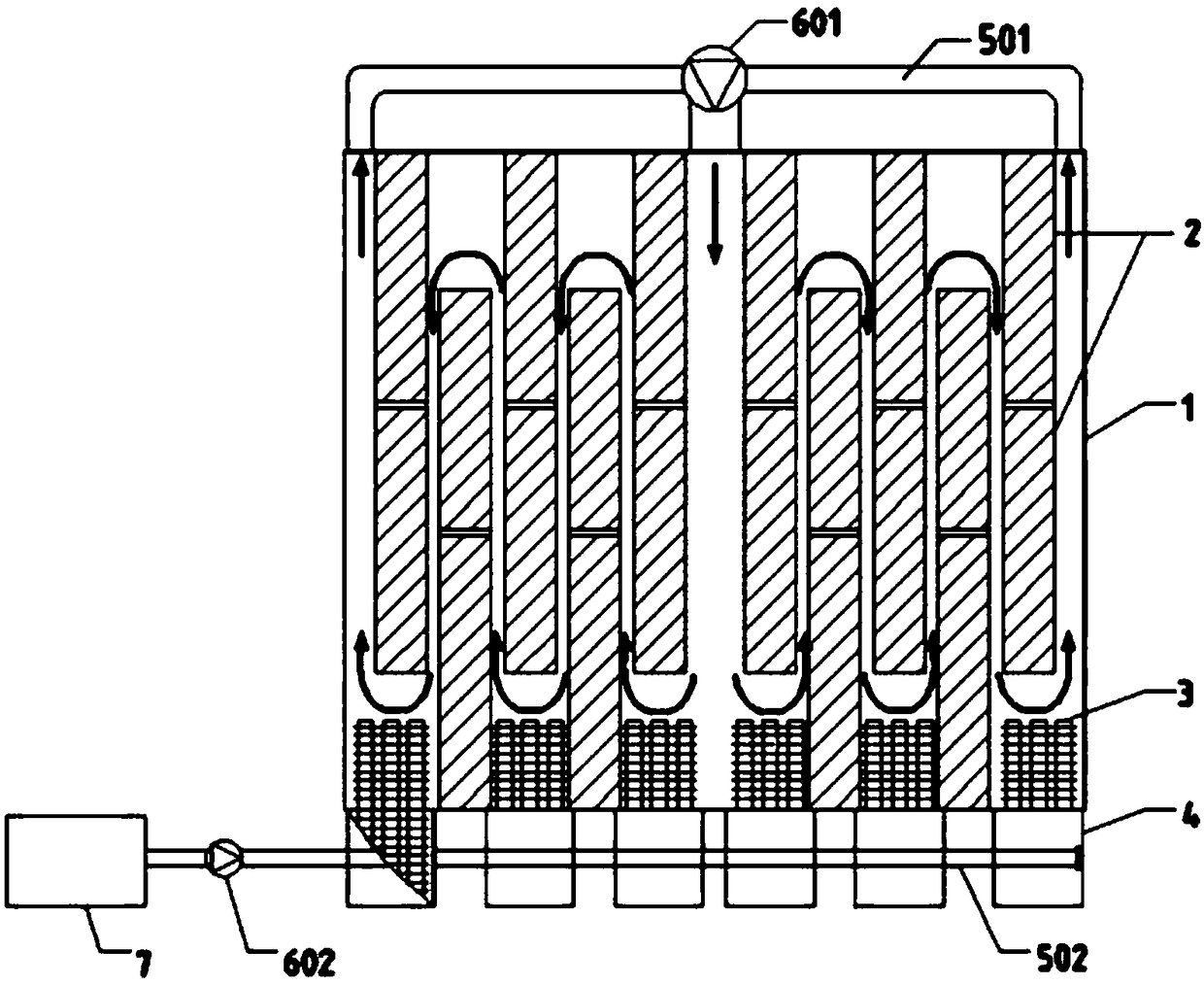
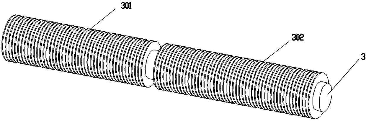
[0033] see Figure 1-3The shown data center immersion liquid cooling cabinet based on heat pipe technology, the immersion liquid cooling cabinet includes: a liquid cooling cabinet 1, an additional refrigerator 4, a first refrigerant circulation pipeline and a second refrigerant circulation pipeline, a pluralit...


PUM


Abstract

The invention discloses a data center immersed-type liquid-cooling cabinet based on the heat pipe technology. A plurality of added cooler cabinets are vertically arranged outside a first side wall ofthe liquid-cooling cabinet. A plurality of server groups are disposed in a length direction parallel to the first side wall at a staggered manner, and are closely attached to the first side wall and asecond side wall facing the first side wall at intervals so as to form a first flow channel. A first refrigerant circulation pipe is communicated with the first flow channel. The interior of each added cooler cabinet is vertically provided with a plurality of heat pipe groups, and each heat pipe group comprises a plurality of horizontal heat pipes. A part of heat pipes stretch into the liquid-cooling cabinet, and are fixedly connected to the added cooler cabinets in a sealed manner. The interior of each added cooler cabinet forms a second flow channel through the gaps between the heat pipes,and a second refrigerant circulation pipe is communicated with the second flow channel and is connected with a refrigerating machine. The liquid-cooling cabinet can quickly dissipate the heat of a server, reduces local hotspots of the cabinet, improves the overall heat dissipation efficiency of a machine room, and reduces the energy consumption of a data center heat dissipation system.

Description

technical field [0001] The invention relates to a liquid cooling device, in particular to a data center submerged liquid cooling cabinet based on heat pipe technology. Background technique [0002] The IDC (Internet Data Center, Internet Data Center) computer room has become an important part of the development of the national economy, and is the infrastructure for promoting the informatization and digitization of the national science and technology industry. With the increase in the scale of data centers and the popularity of blade servers with high heating power, the heat density of cabinets has increased sharply. On the one hand, the heat dissipation of high heat density servers has become an urgent problem to be solved. The equipment shuts down, causing huge losses; on the other hand, the power of cooling equipment required for heat dissipation is doubled, further increasing the energy consumption of the data center. [0003] According to the survey by the Lawrence Berk...

Claims


Application Information

Patent Timeline
IPC IPC(8): H05K7/20
CPCH05K7/203H05K7/20781H05K7/20818
Inventor 饶政华郑思洋李铖灏廖胜明
Owner CENT SOUTH UNIV
Why Eureka
Try Eureka